
| “This site contains affiliate links for which OEMDTC may be compensated” |
A16-101
March 31, 2017
06141 Version 3
Warranty Extension: 2012–13 Insight Oil Consumption Exceeds Customer Expectations
Supersedes 15-015, dated March 17, 2017, to revise the information highlighted in yellow Replaces 15-015, 2012–13 Insight Oil Consumption Exceeds Customer Expectations
AFFECTED VEHICLES
| Year | Model | Trim | VIN Range |
| 2012–13 | Insight | ALL | Check the iN VIN status for eligibility |
REVISION SUMMARY
Under REQUIRED MATERIALS, the oil was changed to Full Synthetic Engine Oil, P/N 08798-9063.
BACKGROUND
The oil control rings may become clogged with carbon deposits. These deposits restrict the ability to scrape and return oil from the cylinder walls to the crankcase, which can result in misfires, engine cylinder damage, engine cylinder head damage, and/or engine oil consumption that may exceed customer expectations.
To increase customer confidence, American Honda is extending the warranty on the engine related to engine oil consumption to 8 years from the original date of purchase with no mileage limit.
The warranty extension does not apply to any vehicle that has ever been declared a total loss or sold for salvage by a financial institution or insurer, or has a branded or similar title under any state’s law.
CUSTOMER NOTIFICATION
Owners of affected vehicles will be sent a notification of this campaign.
Do an iN VIN status inquiry to make sure the vehicle is shown as eligible.
CORRECTIVE ACTION
If the customer complains of oil consumption, do the oil consumption test. If the test shows excessive consumption, then disassemble and inspect the engine. In most cases, you will need to replace the pistons, piston pins, rings and spark plugs.
PARTS INFORMATION
| Part Name | Part Number | Quantity |
| Connecting Rod Bolt (if needed) | 13204-PWA-003 |
8 |
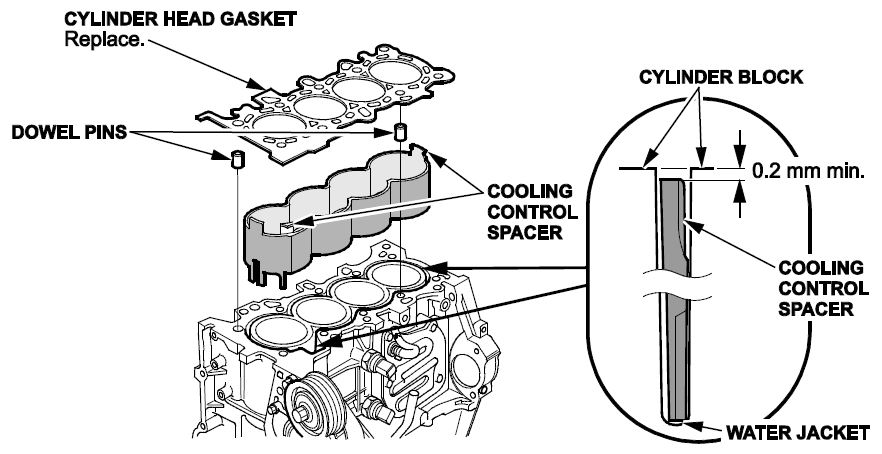
| Cylinder Head Gasket | 12251-RB0-004 |
1 |
| Drain Plug Washer (14 mm) | 94109-14000 |
1 |
| EGR Pipe A Gasket | 18716-RB0-G01 |
1 |
| EGR Pipe B Gasket | 18719-RNA-A01 | 1 |
| Flange Bolt (12 mm x 45 mm) | 90174-TM5-000 | 3 |
| Flange Nut (12 mm) | 90213-SAA-000 | 2 |
| Flexible Exhaust Gasket | 18229-TF0-013 |
1 |
| Head Bolt Washer (9 mm x 155 mm) (if needed) | 90008-PWA-003 |
9 |
| Head Bolt Washer (9 mm x 165mm) (if needed) | 90008-RMX-003 |
1 |
| Intake Manifold Gasket | 17105-RBJ-007 |
4 |
| Oil Filter | 15400-PLM-A01 |
1 |
| Oil Pan Gasket | 11252-PWA-000 |
1 |
| O-Ring | 91333-PNC-006 | 1 |
| O-Ring (8.8 mm X 1.9 mm) | 91302-GE0-000 |
1 |
| O-Ring (17.8 mm x 2.4 mm) | 11203-PWA-003 |
1 |
| Oil Strainer Gasket | 15221-PZ1-000 |
1 |
| Sealing Washer (28 mm) | 90401-PR4-000 |
1 |
| Spark Plugs | 12290-RW0-003 |
8 |
| Piston Kit (contains 4 pistons, 4 pins, and 4 ring packs.) | 06131-RBJ-305 | 1 |
| TWC Gasket | 18115-RB0-004 |
1 |
REQUIRED MATERIALS
| Part Name | Part Number | Quantity |
| Honda Bond 4 (one tube will repair 5 vehicles) |
08717-1194 | 1 |
| Full Synthetic Engine Oil | 08798-9063 |
4 |
| Honda Long-Life Antifreeze/Coolant Type 2 | OL999-9011 | 1 |
TOOL INFORMATION
| Part Name | Tool Number | Quantity |
| Piston Base | 07973-6570500 or 07973-657A500 | 1 |
| Piston Base Head/Insert | 07TGF-001000A | 1 |
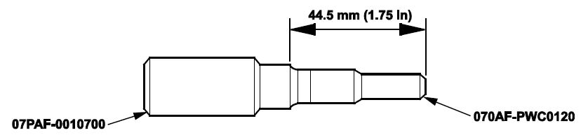
| Insert Pin | 07PAF-0010700 or 07PAF-001A700 | 1 |
| Piston Base Spring | 07973-6570600 or 07973-657A600 | 1 |
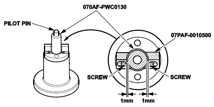
| Pilot Collar OD 18 mm | 070AF-PWC0130 or 070AF-PWCA130 | 1 |
| Insert Adjust | 070AF-PWC0120 or 070AF-PWCA120 | 1 |
| Pilot Pin | 070AF-PWC0110 or 070AF-PWCA110 | 1 |
| 73 mm Piston Ring Compressor | SCP1473 (or equivalent) | 1 |
| Engine Hanger | AART1256 | 1 |
These tools are available through the Honda Tool and Equipment Program at 888-424-6857. Verify that these tools are on hand before scheduling the repair.
WARRANTY CLAIM INFORMATION
NOTE: You must do an oil consumption test first. Refer to the job aid Engine Oil Consumption Test. If the oil consumption test doesn’t indicate excessive engine oil consumption, this warranty extension does not apply, continue with normal troubleshooting.
| Operation Number | Description | Flat Rate Time | Defect Code | Symptom Code | Template ID | Failed Part Number |
| 1111DV | Do the engine oil consumption test and, if necessary, replace all 4 pistons, pins, rings and all 8 spark plugs. | 8.4 hrs | 6C100 | KD000 | 16-101A | 13010-RBJ-J00 |
| 1111DV | Do the engine oil consumption test and, if necessary, replace all 4 pistons, pins, rings, all 8 spark plugs. | 8.4 hrs | 6C100 | KD000 | 16-101B | 13010-RBJ-J00 |
| A | Add – Replace new cylinder head. | 0.5 hr | ||||
| 1111DW | Do the engine oil consumption test and, if necessary, replace the short block. | 8.6 hrs | 6C100 | KD000 | 16-101C | 13010-RBJ-J00 |
| 1111DW | Do the engine oil consumption test and, if necessary, replace the short block. | 8.6 hr | 6C100 | KD000 | 16-101D | 13010-RBJ-J00 |
| A | Add – Replace new cylinder head | 0.5 hr |
Skill Level: Repair Technician
DIAGNOSIS
- Do an engine oil consumption test. Refer to the job aid Engine Oil Consumption Test.
- Review the results of the engine oil consumption test.
- Based on the test results, if the engine is consuming an unusually high amount of oil, contact your DPSM for approval, then go to REPAIR PROCEDURE.
- Based on the test results, if the engine is consuming a normal amount of engine oil, the vehicle is OK. Have the service advisor explain to the customer that the vehicle is OK, and that the consumption of oil is within a normal range.
NOTE: Have the service advisor remind the customer to check the engine oil level every time the fuel tank is filled. Modern engines require less frequent oil changes, which may impact the amount of oil used between oil changes.
REPAIR PROCEDURE
NOTE:
- IMA components are located in this area. The IMA is a high-voltage system. You must be familiar with the IMA system before working on or around it. Make sure you have read the IMA service precaution before doing repairs or service.
- Before removing the engine/transmission, read the Service Precautions for the IMA System. Refer to the service information.
- To avoid damaging the wiring and terminals, unplug the wiring connectors carefully while holding the connector portion.
- Mark all wiring and hoses to avoid misconnection at reassembly. Also, be sure that they do not contact other wiring or hoses, or interfere with other parts.
The following electronic service manual procedures have been used in full or in part within this service bulletin. For more detail on these procedures and torque specifications, refer to the electronic service manual.
- IMA System Service Precautions
- Windshield Wipers & Cowl Removal
- Fuel Pressure Relieving
- Air Cleaner Assembly Removal
- Intake Manifold Removal and Installation
- Engine Oil Replacement
- Coolant Replacement
- Drive Belt Removal/Installation
- Warm-Up TWC Removal/Installation
- Cam Chain Removal
- Cylinder Head Removal
- Valve Adjustment
- Oil Pan Installation
- PCM Idle Learn Procedure
- Turn the battery module switch OFF.
- Remove the windshield wipers and cowl cover.
- Relieve the fuel pressure.
- Drain the radiator. Drain the coolant from the engine block by removing the rear drain plug on the backside of the block.
NOTE: Collect coolant in a clean container for re-use. Reinstall the 28 mm drain bolt using a new washer when coolant is completely drained.
- Disconnect the negative cable from the 12-volt battery.
- Remove the air cleaner assembly.
- Remove the intake manifold, and leave the throttle body in place.
- Remove the eight ignition coils.
- Disconnect the following engine wire harness connectors and wire harness clamps from the cylinder head:
- Four injector connectors
- ECT sensor 1 connector
- CMP sensor connector
- Secondary HO2S connector
- Rocker arm oil control solenoid connector
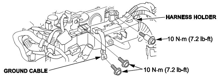
- Remove the harness holder and disconnect the breather hose.
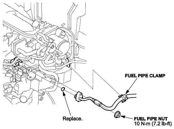
- Remove the fuel pipe nut and the fuel pipe clamp. Hold a shop towel around the fuel pipe as fuel will leak out while disconnecting.
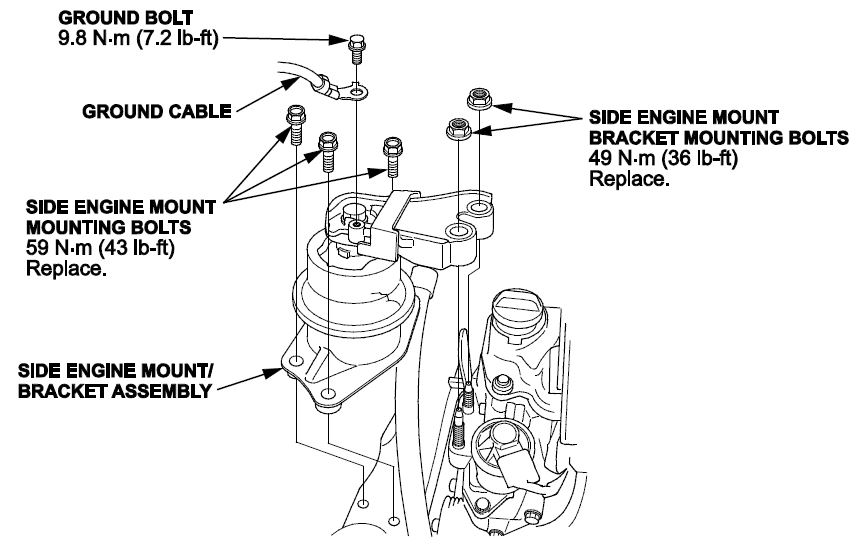
- Remove the harness holder mounting bolts and the ground cable, then remove the harness holder.
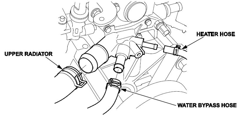
- Disconnect the upper radiator hose, the water bypass hose, and the heater hose from the cylinder head assembly.
- Remove the drive belt.
- Remove the warm-up TWC.
CAM CHAIN REMOVAL
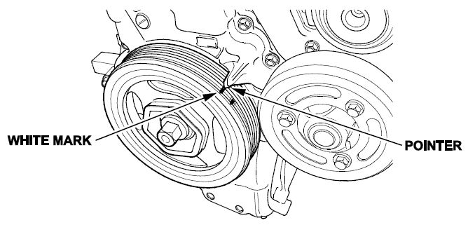
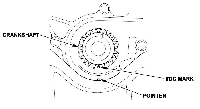
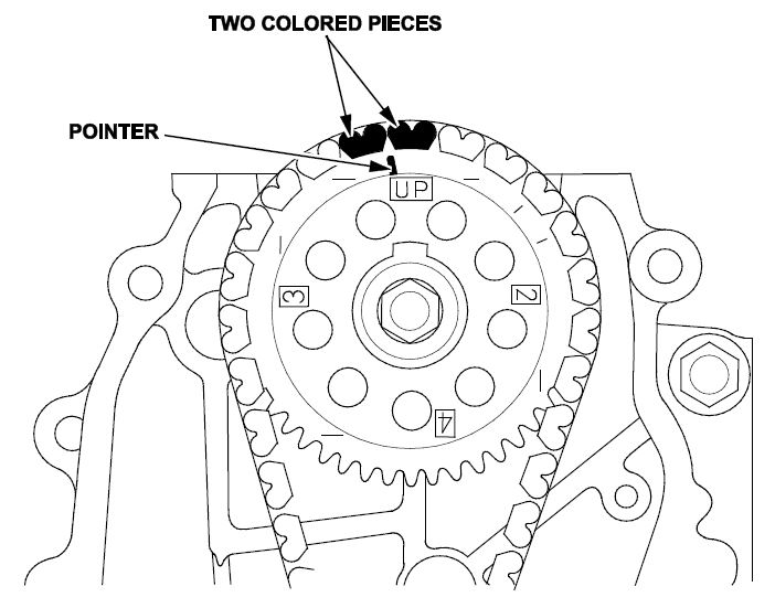
- Turn the crankshaft so its white mark lines up with the pointer.
- Remove the cylinder head cover.
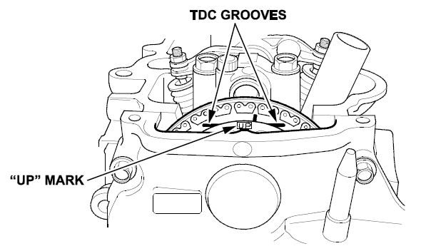
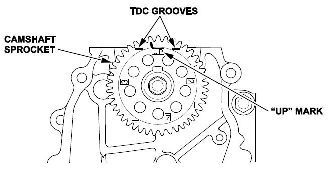
- Check the No. 1 piston at top dead center. The “UP” mark on the camshaft sprocket should be at the top, and the TDC grooves on the camshaft sprocket should line up with the top edge of the head.
- Remove the right front wheel.
- Remove the splash shield.
- Remove the water pump pulley.
- Remove the crankshaft pulley.
- Support the engine with a jack and a wood block under the oil pan.
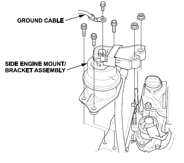
- Remove the ground cable, then remove the side engine mount/bracket assembly.
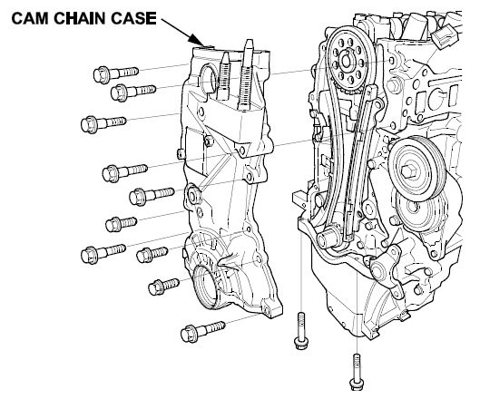
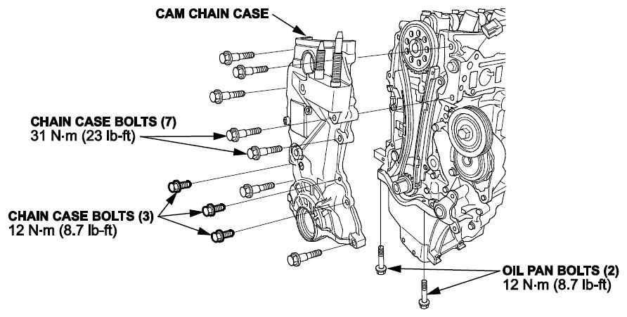
- Remove the cam chain case.
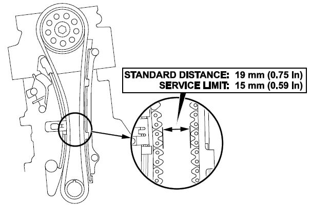
- Measure the cam chain separation. If the distance is less than the service limit, replace the cam chain and the cam chain tensioner.
- Remove the cam chain tensioner and cam chain guides.
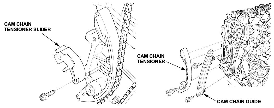
- Remove the cam chain.
CYLINDER HEAD REMOVAL AND INSPECTION
- Remove the cylinder head bolts. To prevent warpage, loosen the bolts in sequence 1/3 turn at a time. Repeat this sequence until all of the bolts are removed.
- Remove the cylinder head and visually inspect the head of the valves on the combustion side of the cylinder head for damage.
NOTE: This is only a visual inspection looking for damage to the valves.
- If any of the valves show any signs of damage, replace the cylinder head and go to CYLINDER BORE INSPECTION.
- If the valves are ok, go to step 3.
- Visually inspect each of the spark plugs for damaged or melted pieces of the center electrode or ground electrode.
- If any of the spark plug shows signs of damage, remove the valve closest to the damaged plug from the cylinder head and go to step 4.
- If the spark plugs are ok, go to CYLINDER BORE INSPECTION.
- Visually inspect the cylinder head valve seat and the valve seat face for damage.
- If there are any signs of damage (physical or local heat buildup) replace the cylinder head and go to CYLINDER BORE INSPECTION.
- If the valves and valves seats are ok, reassemble the cylinder head, and go to CYLINDER BORE INSPECTION.
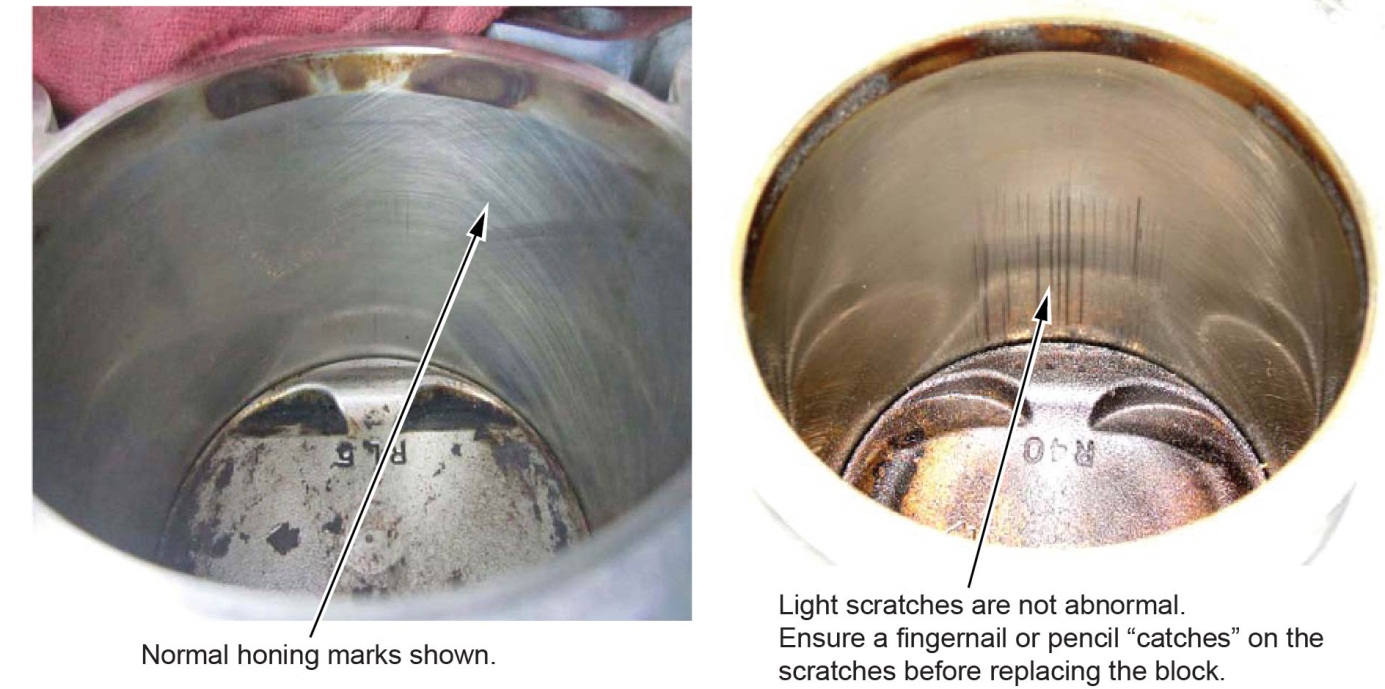
CYLINDER BORE INSPECTION
- Check the cylinder walls by rubbing your fingernail or a pencil with light pressure perpendicular to any vertical scratches that are in the cylinder bore.
- If your fingernail or a pencil does not catch on the scratches, the cylinder block is OK. Go to INSTALLATION OF ENGINE SUPPORT.
- If your finger nail or pencil catches on the scratches, replace the engine short block. Go to SHORT BLOCK REPLACEMENT to replace the engine.
NOTE:
- If the short block is replaced, it already has the counter-measured pistons and rings installed.
- The oil pans that come with the short block aren’t fully sealed. There is a gasket inside the oil pan that needs to be installed before sealing the oil pan. For more information, refer to PIB 16-0001.
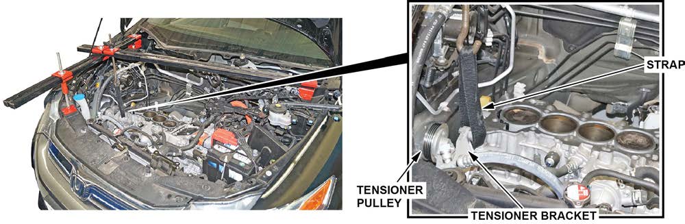
INSTALLATION OF ENGINE SUPPORT
- Use two support bars in a T-configuration to support the front end of the short block with a suitable strap through the tensioner bracket.
OIL PAN REMOVAL
- Raise the vehicle.
- Drain the engine oil.
- Remove the driveshaft heat shield bolt from the engine oil pan.
- Remove the A/C compressor without disconnecting the A/C lines. Support the compressor with a strap to prevent it from hanging on the A/C lines.
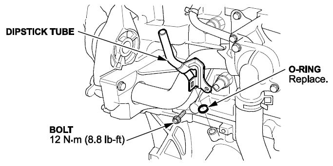
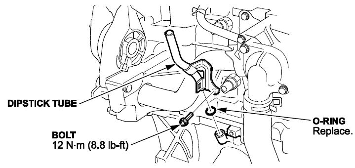
- Remove the dipstick, then remove the dipstick tube.
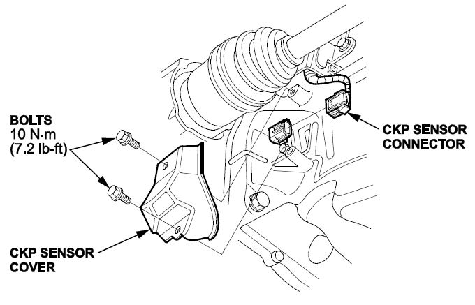
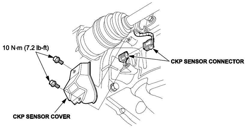
- Remove the CKP sensor cover, then disconnect and remove the CKP sensor connector.
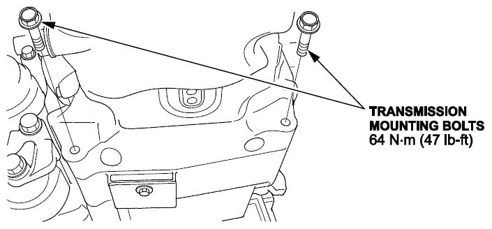
- Remove the transmission mounting bolts.
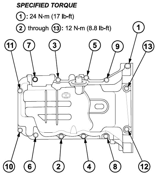
- Remove the oil pan bolts.

- Using a flat-blade screwdriver, separate the oil pan from the engine block in the places shown.
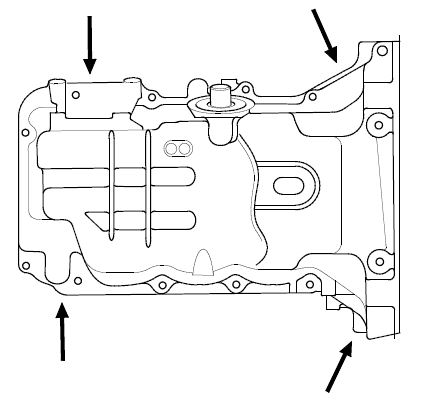
- Remove the oil pan.
NOTE: Lower the oil pan carefully to avoid damaging the IMA motor rotor position sensor.
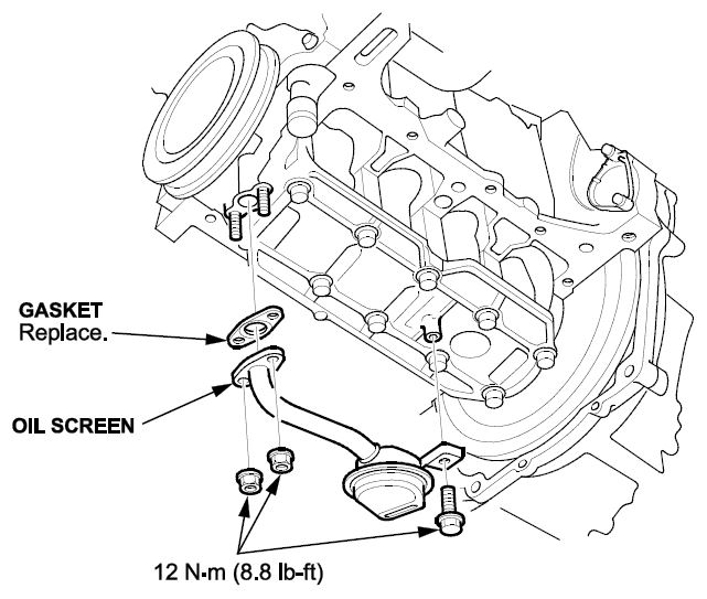
- Remove the oil screen.
REMOVAL OF PISTONS AND RODS
NOTE: Before and during removal of pistons, rods, and caps, mark each piston top with the cylinder number and direction mark towards the front of the engine.
- Prepare your work bench with a number location for each piston rod assembly to ensure the rods and caps are not mixed as they are not interchangeable. The numbers stamped across the side of the rod and cap does not indicate the cylinders they came from; they are a manufacturing number.
- Install the crank pulley and the key on the crank without the bolt.
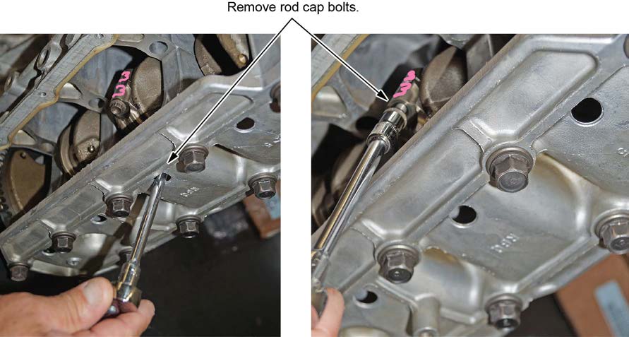
- Beginning with cylinder No. 2 and 3 at Bottom Dead Center (BDC), rotate the crank slightly until the rod cap bolts align with the holes on the main bearing cap bridge. Mark the caps to the rods with a grease pen as shown below.
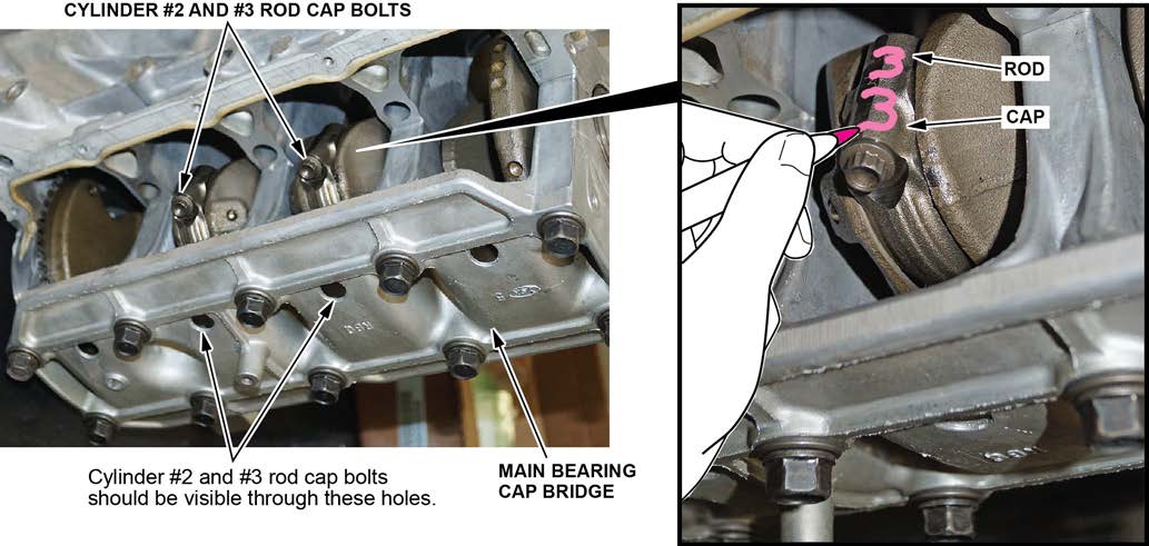
- Using a ¼ inch drive 8 mm 12-point socket (Snap-On TMMD8 or equivalent), loosen and remove the rod caps for cylinders No. 2 and 3, then set the caps on the bench next to the corresponding numbers.
- Using a wooden or plastic handled hammer, gently push the pistons and rod assemblies No. 2 and 3 out of the short block.
- Rotate the crankshaft 180 degrees, then repeat steps 3, 4, and 5 on cylinders No. 1 and 4.
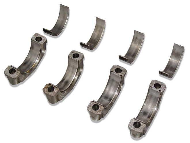
- Visually inspect all connecting rod bearings for signs of damage.
NOTE: If your fingernail catches on a scratch or groove in the bearing, replace it. Pictured are normal, reusable rod bearings after about 35,000 miles. Some discoloration is normal and does not require replacement.
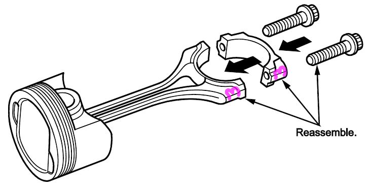
- Reassemble the rod caps on the corresponding rods.
PISTON & PIN REPLACEMENT
Special Tools Required
| Part Name | Tool Number | Quantity |
| Piston Base | 07973-65700500 or 07973-657A500 | 1 |
| Piston Base Head | 07PAF-0010400 or 07PAF-001A400 or 07TGF-001000A | 1 |
| Piston Base Head Insert | 07PAF-0010500 or 07PAF-001A500 or 07TGF-001000A | 1 |
| Insert Pin | 07PAF-0010700 or 07PAF-001A700 | 1 |
| Piston Base Spring | 07973-6570600 or 07973-657A600 | 1 |
| Pilot Collar OD 18 mm | 070AF-PWC0130 or 070AF-PWCA130 | 1 |
| Insert Adjust | 070AF-PWC0120 or 070AF-PWCA120 | 1 |
| Pilot Pin | 070AF-PWC0110 or 070AF-PWCA110 | 1 |
Disassembly
- Assemble the special tool as shown.
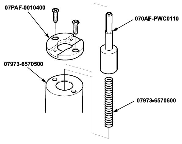
- Temporarily install the pilot collar over the pilot pin and adjust the piston base head insert as shown. Then tighten the screws. Remove the pilot collar.
- Assemble and adjust the length of the insert pin and insert adjust to 44.5 mm.
- Starting with rod assembly No. 1, clearly mark the rod with the piston number. With the arrow on top of the piston pointing up, place the piston assembly on the piston base head. Make sure you position the recessed flat area of the piston against the piston base head insert as shown.
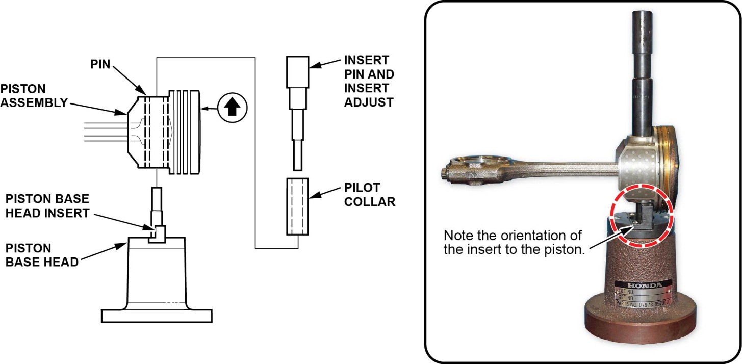
- Press the pin out with the insert pin, the insert adjust tool, the pilot collar, and a hydraulic press.
- Repeat steps 4 and 5 on pistons No. 2, 3, and 4. Do not reuse the old pistons and pins.
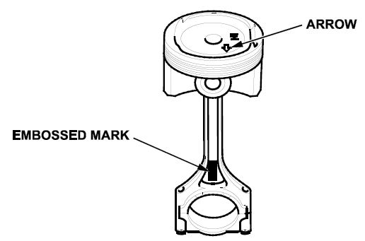
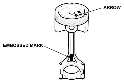
- Starting with piston No. 1, assemble the piston and the connecting rod with the arrow and the embossed mark on the same side.
- Insert the pilot collar into the piston and the connecting rod.
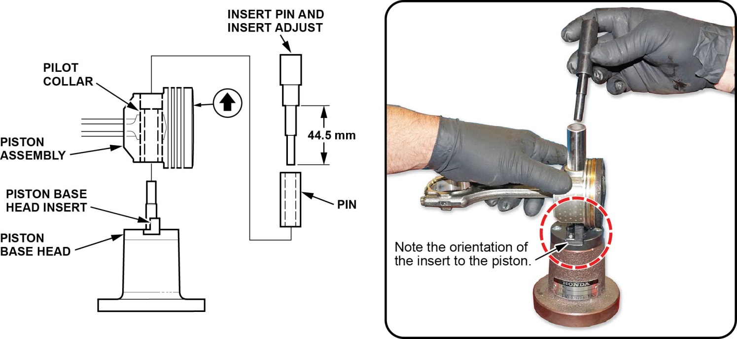
- With the arrow on top of the piston and the embossed mark on the connecting rod facing up, place the piston assembly on the piston base head. Be sure you position the recessed flat area of the piston against the area of the piston base head insert as shown.
- Press the piston pin in using the insert pin, the insert adjust, and a hydraulic press.
- Repeat steps 8 thru 10 with pistons No. 2, 3, and 4.
Assemble New Rings on new pistons
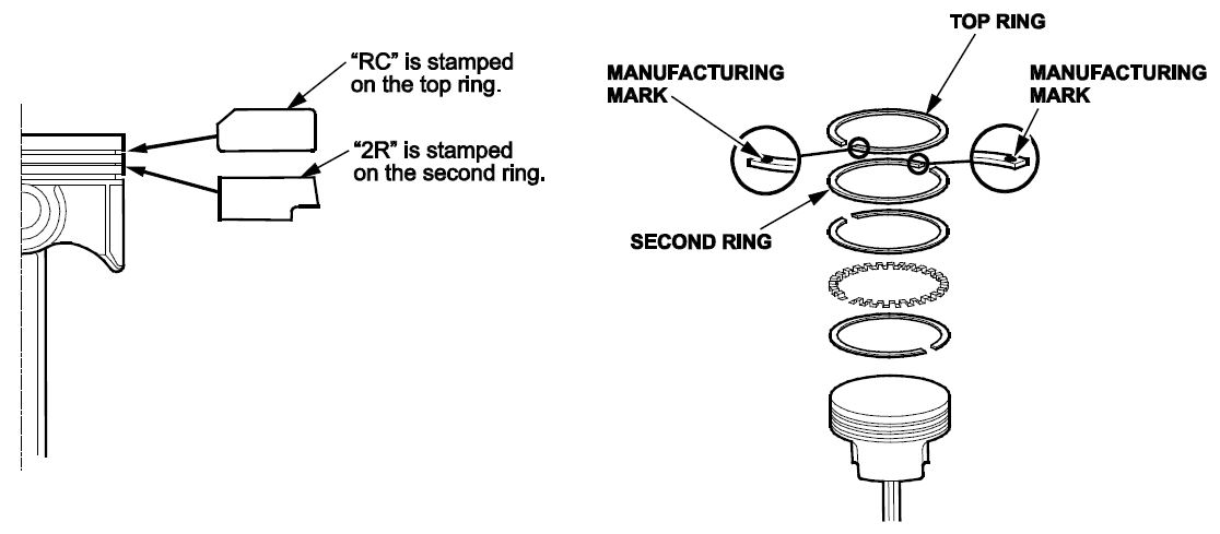
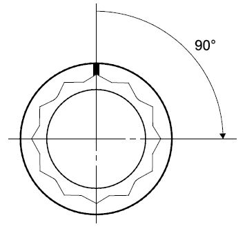
- Install the rings as shown. The top ring has an “RC” mark, and the second ring has a “2R” mark. The manufacturing marks must face upward.
- Rotate the rings in their grooves to make sure they do not bind.
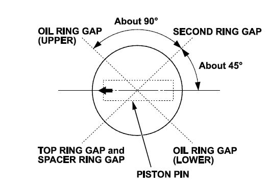
- Position the ring end gaps as shown.
- Repeat steps 1 thru 3 on the remaining three piston assemblies.
Piston Installation
- Rotate the crankshaft so that cylinders No. 1 and 4 journals are at bottom dead center (BDC).
- Remove the connecting rod cap to piston No. 1 and check that the bearing is securely in place.
- Apply new engine oil to the entire piston, the inside of the ring compressor, the cylinder bore, and the rod bearings.
- Position the embossed mark on the rod to face the cam chain end of the engine block.
- Set the piston in the ring compressor and position it in the cylinder, noting the rod/cap marks that you made in step 3 of REMOVAL OF PISTONS AND RODS.
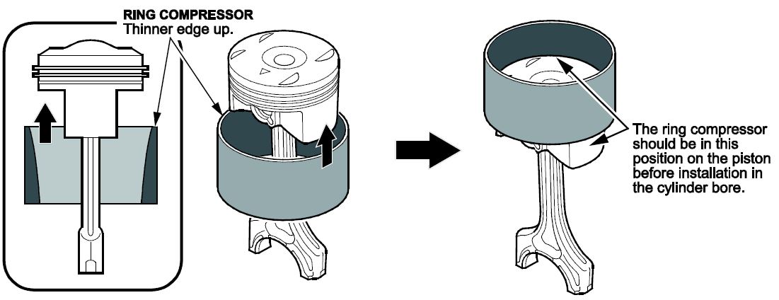
- Set the ring compressor on the piston bore, then push the piston in with your hands.
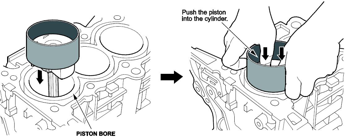
- Stop after the ring compressor pops free, and check the connecting rod-to-rod journal alignment before pushing the piston into place.
- Measure the diameter of each connecting rod bolt at point A and point B with a micrometer.
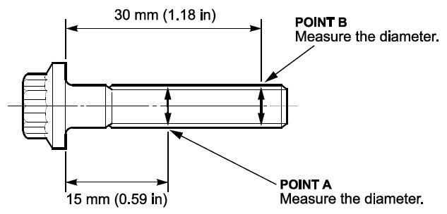
- 9Calculate the difference in diameter between point A and point B.
Point A – Point B = Difference in diameter
Difference in Diameter
Specification: 00.05 mm (00.002 in)
- If the difference in diameter is out of tolerance, replace the connecting rod bolts.
- Apply new engine oil to the bolt threads, then install the rod caps with the bearings. Rotate the crankshaft slightly off BDC in order to line up the cap bolts with the access hole on the main bearing bridge.
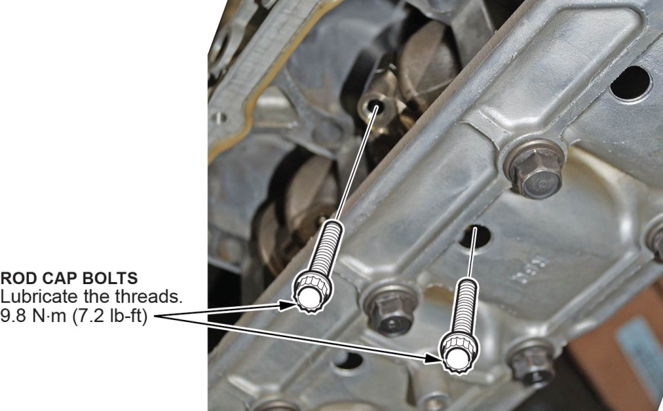
- Torque the bolts to 8 N·m (7.2 lb-ft).
- Tighten the connecting rod bolts an additional 90 degrees.
NOTE: Remove the connecting rod bolt if you tightened it beyond the specified angle, and go back to step 12 and 13 of the procedure. Do not loosen it back to the specified angle
- Repeat steps 8 thru 13 to install piston No. 4.
- Rotate the crankshaft 180 degrees and repeat steps 8 thru 13 to install pistons No. 2 and 3. Install the oil screen and gasket. Then torque the nuts to 12 N·m (8.8 lb-ft).
Oil Pan Installation
- Remove all of the old liquid gasket from the oil pan mating surfaces, the bolts, and the bolt holes.
- Clean and dry the oil pan mating surfaces and the O-ring groove.
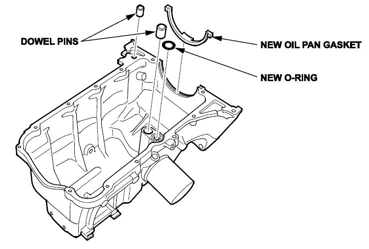
- Install the new oil pan gasket, the new O-ring, and the dowel pins on the oil pan.
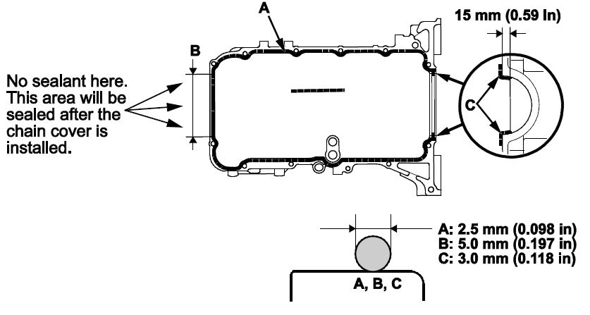
- Apply liquid gasket (P/N 08717-0004, 08718-0003, or 08718-0009) to the engine block mating surface of the oil pan and to the inside edge of the bolt holes but not on the mating surfaces for the timing chain cover. Install the component within 5 minutes of applying the liquid gasket.
NOTE:
- Apply a 2.5 mm (0.098 in)-diameter bead of liquid gasket along the broken line A.
- Apply a 5.0 mm (0.197 in)-diameter bead of liquid gasket to the shaded area B.
- Apply a 3.0 mm (0.118 in)-diameter bead of liquid gasket to the broken line C.
- If you apply liquid gasket P/N 08718-0012, the component must be installed within 4 minutes.
- If too much time has passed after applying the liquid gasket, remove the old liquid gasket and residue, then reapply new liquid gasket.
- Install the oil pan.
NOTE:
- Raise the oil pan carefully to avoid damaging the IMA motor rotor position sensor.
- Wait at least 30 minutes before filling the engine with oil.
- Do not run the engine for at least 3 hours after installing the oil pan.
- Make sure to install the bolts in the correct locations according to size.
- Tighten the bolts in three steps. Wipe off the excess liquid gasket from the crankshaft pulley end and timing chain cover sealing surface along with the drive plate end.
NOTE: Omit bolts 10 and 11 in the torque sequence. They are not installed until the front timing chain cover is installed.
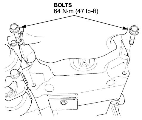
- Install the transmission mounting bolts and torque them to 64 N·m (47 lb-ft).
- Install and connect the CKP sensor connector. Then install the CKP sensor cover and torque the bolts to 10 N·m (7.2 lb-ft).
- Install the A/C compressor.
- Install the driveshaft heat shield.
- Lower the vehicle and support the engine with a jack and a wood block under the oil pan.
- Remove the engine support assembly.
- Install the dipstick tube with a new O-ring and torque the bolt to 12 N·m (8.8 lb-ft). Then install the dipstick.
- Install the new cylinder head gasket and the dowel pins on the engine block. Always use a new cylinder head gasket.
- Set the crankshaft to top dead center (TDC). Align the TDC mark on the crankshaft sprocket with the pointer on the oil pump.
- Set the camshaft TDC. The “UP” mark on the camshaft sprocket should be at the top and the TDC grooves on the camshaft sprocket should line up with the top edge of the head.
- Install the cylinder head on the engine block.
- Install the cam chain on the crankshaft sprocket with the colored piece aligned with the TDC mark on the crankshaft sprocket, then install the crankshaft sprocket with the special key to the crankshaft.
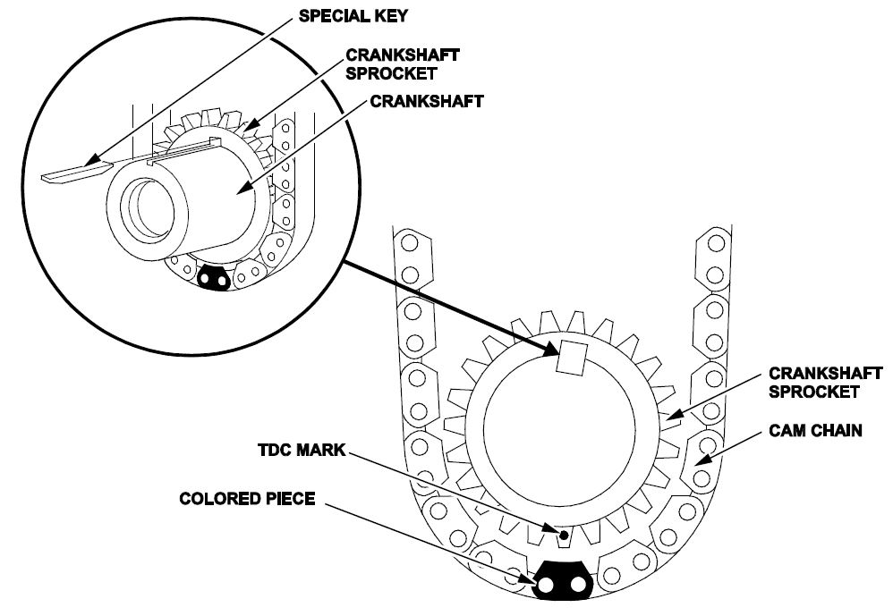
- Install the cam chain on the camshaft sprocket with the pointer aligned with the center of the two colored pieces as shown.
- Install the water pump pulley.
- Apply new engine oil to the threads and flange of all cylinder head bolts.
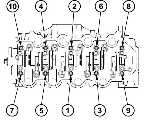
- Torque the cylinder head bolts in the sequence shown to 29 N·m (22 lb-ft) with a beam-type torque wrench if possible. When using a preset click-type torque wrench, be sure to tighten slowly and do not over tighten. If a bolt makes any noise while you are torqueing it, loosen the bolt and retighten it from the first step.
NOTE: The long head bolt goes in the number 9 location in the torque sequence.
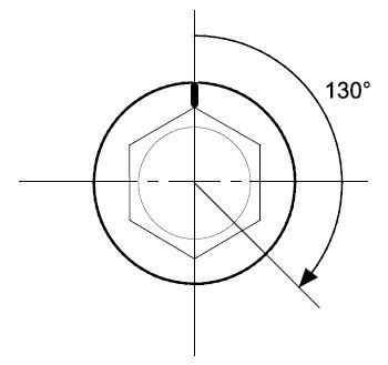
- Tighten all cylinder head bolts an additional 130 degrees.
- Install the cam chain and cover.
- Install the cylinder head cover.
- Install the side engine mount using new bolts.
- Install the warm-up TWC with a new gasket.
- Install the drive belt.
- Connect the upper radiator hose, the water bypass hose, and the heater hose.
- Inspect the valve clearance and adjust it if needed.
- Reinstall the cylinder head cover.
- Install the engine harness and ground cable. Then install the fuel pipe nut and the fuel pipe clamp using a new O-ring.
- Connect the engine wire harness connectors and install the wire harness clamps to the cylinder head:
- Four injector connectors
- ECT sensor 1 connector
- CMP sensor connector
- Secondary HO2S connector
- Rocker arm oil control solenoid connector
- Remove the spark plugs and replace them with new ones.
- Install the eight ignition coils but leave the connectors unplugged. Install the intake manifold and the air cleaner. Reconnect the battery negative cable.
- Inspect for fuel leaks. Turn the ignition switch to ON (II) (do not operate the starter) so the fuel pump runs for about 2 seconds and pressurizes the fuel line. Repeat this operation three times, then check for fuel leakage at any point in the fuel line.
- Refill the radiator using the saved coolant and top off with the new coolant as needed. Then bleed the air from the cooling system.
- Fill the engine with oil.
- Crank the engine for about 5 seconds to prime the engine with oil before plugging in the ignition coils.
- Connect the ignition coils and do the idle learn procedure.
SHORT BLOCK REPLACEMENT
NOTE:
- When you replace the short block, do not replace the pistons or rings; the new block already has the counter-measured pistons and rings installed.
- The oil pan isn’t fully sealed. There is a gasket inside the oil pan that needs to be installed before sealing the oil pan. For more information, refer to PIB 16-0001.
- Remove/disconnect any remaining hoses, connectors, and components so you can remove the short block and IMA motor assembly. Refer to service information.
- Raise the vehicle.
- Remove the lower transmission housing bolts, the drive plate bolts, and any other brackets and bolts that secure the transmission to the short block and IMA assembly. Support the short block and IMA motor assembly and transmission with a floor jack under the transmission bell housing area. See service information.
- Set up an engine hoist with a sling to remove the short block and IMA motor.
NOTE: You won’t use the engine hanger as described in the service information to remove the block.
- Remove the upper transmission housing bolts and separate the short block and IMA motor assembly from the transmission.
- Remove the short block and IMA motor assembly from the vehicle and place the assembly on a work bench or other suitable work surface.
- Separate the short block from the IMA motor.
- Place the replacement short block on an engine stand and remove the oil pan.
NOTE: The oil pan does not come sealed. You will properly install it in step 9.
- Install the cylinder head, cam chain, cam chain cover, and oil pan. Refer to service information.
NOTE: AHM recommends installing the intake and exhaust manifolds after installing the engine and IMA motor assembly in the vehicle.
- Install the engine and IMA motor assembly in the vehicle. Refer to service information.
- Reinstall all remaining parts in the reverse order of removal and refill all fluids.
- Use the HDS to complete the PCM idle learn procedure.
END
 Loading...

- Full synthetic 0W-20 engine oil that is made with natural gas and designed for complete protection for top engine performance
- Helps extend engine life and protects for up to 15 years or 500,000 miles, whichever comes first. Guaranteed* (see Warranty Information in Product Description).
- Provides better fuel economy (based on the latest industry standards)
- Pennzoil Platinum 0W-20 keeps pistons up to 45% cleaner than the toughest industry standard (based on Sequence IIIH results)
- No other leading synthetic oil provides better wear protection from friction (Based on Sequence IVA wear test using SAE 5W-30)

- Superior wear protection on critical engine parts
- 6X better wear protection than industry standards, as measured in the latest Sequence IVA test
- Superior sludge cleaning and protection against new formation
- 1.3X better sludge protection than industry standards, as measured in Sequence VH sludge test vs. API SP limits
- Full synthetic formula provides thermal and oxidation stability

- Mobil 1 Extended Performance full-synthetic motor oil 0W-20 helps protect critical engine parts for up to 20,000 miles between oil changes,* controlling oxidation to prevent oil breakdown and maintaining excellent viscosity
- Utilizes Mobil 1’s Triple Action+ Formula to combine outstanding engine performance, protection, and cleanliness with the added benefit of power
- Meets ILSAC GF-6 standards to help provide low-speed pre-ignition (LSPI) and timing chain wear protection while keeping your engine clean and helping to improve your fuel economy
- Helps extend engine life by working to prevent damaging deposits and sludge buildup
- Provides excellent internal engine heat protection (up to 500 degrees F) and low temperature protection (to -40 degrees F)
- Advanced protection against the four main causes of engine breakdown: wear friction heat and deposits
- 40% better wear protection vs. industry standards as tested in the Sequence IVB engine test
- 25% better deposit protection with superior engine cleaning detergents as tested in the GMOD engine test
- Full synthetic formula offers 24X stronger protection against engine-killing contaminants than the leading full synthetic motor oil
- Meets or exceeds all requirements of ILSAC GF-6A, API SP, API SN with SN Plus, API SN, GM dexos 1 Gen 5

- Full synthetic 0W-20 motor oil provides strong engine performance and protection against deposits between oil changes
- Provides improved fuel economy (based on the latest industry standard)
- Designed to provide more performance with superior lubrication flow and pumpability at high and low temperatures (compared to Quaker State conventional and synthetic blend motor oils).
- Formulated with high resistance to oxidation, keeping the oil fresher for longer.
- Reduces friction to maximize horsepower (compared to Quaker State conventional and synthetic blend motor oils)

- 3X stronger against viscosity breakdown than leading full synthetic, based on Kurt Orbahn test in 5W-30 grade
- 10X better high temperature performance, as measured in Sequence IIIH engine test vs. API SP test limit
- 6X better wear protection, Protection for 10,000 miles between oil changes
- 1.4X better sludge protection, as measured in Sequence VH engine test vs. API SP test limit
- Meets ILSAC GF-6 to prevent low speed pre ignition (LSPI) and timing chain wear protection
- Ultimate protection against wear, friction, heat and deposits, the main reasons for engine breakdown
- 24x stronger protection against engine-killing contaminants than the industry-leading full synthetic
- Dual Defense Additive Technology helps keep your engine clean and running at peak performance for optimal fuel economy and performance
- 10X stronger against oil breakdown and 50% greater wear protection than industry standards
- Meets or exceeds all requirements of ILSAC GF-6A, API SP, API SN with SN Plus, API SN, dexos 1 Gen 6
- Full synthetic formula is engineered with Enhanced MaxLife Technology to prevent engine breakdown in vehicles with over 75,000 miles
- Formulated with seal conditioners to prevent and treat oil leaks, Valvoline Full Synthetic High Mileage minimizes oil consumption and maximizes engine life
- 50% better wear protection than the industry standard and 25% extra defense against deposits, sludge, corrosion and rust
- Meets or exceeds all requirements of ILSAC GF-6A, API SP, API SN with SN Plus, API SN
- American made and formulated, from the Original Motor Oil brand trusted for more than 150 years

- Full synthetic 0W-20 engine oil designed for vehicles with over 70,000 miles that offers the same protection as SAE 5W-20 and is made with natural gas
- Helps extend engine life and protects for up to 15 years or 500,000 miles, whichever comes first. Guaranteed* (see Warranty Information in Product Description).
- Keeps pistons up to 45% cleaner than the toughest industry standard (based on Sequence IIIH results)
- Provides unsurpassed wear protection for your engine (based on Sequence IVA wear test using SAE 5W-30)
- Formulated to deliver less oil burn off than high mileage motor oils made from crude oil
- Better wear protection
- Increased fuel efficiency
- Better protection of the expensive catalytic emission system
- Improved compatibility with fuels containing ethanol
- Superior corrosion protection
Last update on 2024-06-21 / Affiliate links / Images from Amazon Product Advertising API
This product presentation was made with AAWP plugin.