NHTSA ID Number: 10083965
Manufacturer Communication Number: A13-082
Summary
SERVICE BULLETIN – THE PISTON RINGS ON CERTAIN CYLINDERS MAY ROTATE AND ALIGN WHICH CAN LEAD TO SPARK PLUG FOULING. SPARK PLUG FOULING MAY REUSLT IN ROUGH ENGINE IDLE AND/OR ENGINE MISFIRE.
A13-082
May 18, 2015
51869-02164 Version 7
Warranty Extension: MIL Comes On With DTCs P0301 thru P0304
Supersedes 13-082, dated September 12, 2015, to revise the information highlighted in yellow.
AFFECTED VEHICLES
| Year | Model | Trim | VIN Range |
| 2009–13 | Pilot | ALL | Check the iN VIN Status for Eligibility |
REVISON SUMMARY
- Under REPAIR PROCEDURE B – PISTON CLEANING AND RING REPLACEMENT, Replace Parts as Needed for Repair Procedure B, changed bolt count for the 12 x 163 Washer bolt (P/N 90005-PAA-A01) under Cyl 1-4 from 8 to 16. Also changed the bolt count for Connecting Rod Bolt from 8 to 6.
CORRECTIVE ACTION
2009–11 Models: Complete the diagnosis procedure and if necessary, update the PCM software and replace the affected spark plugs. If the vehicle returns after the updated PCM software and spark plug replacement have been installed, clean the pistons and replace the pistons rings along with the spark plugs (Procedure B).
NOTE: Make sure the software update has been completed, spark plugs replaced (Procedure A), and the vehicle returned to the customer before making any additional repairs. Failure to do so will result in claim review by your DPSM and possible debit.
2012–13 Models: Complete the diagnosis procedure and if necessary, clean the pistons and replace the pistons rings along with the spark plugs (Procedure B).
BACKGROUND
American Honda is announcing a powertrain warranty extension as a result of a settlement of a class action captioned, Soto et al.v. American Honda Motor Co., Inc., Case No. 3:12-cv-1377-SI (N.D. Cal.).
The piston rings on certain cylinders may rotate and align, which can lead to spark plug fouling. This can set DTCs P0301 No. 1 cylinder misfire detected, P0302 No. 2 cylinder misfire detected, P0303 No. 3 cylinder misfire detected, P0304 No. 4 cylinder misfire detected, and cause the MIL to come on.
American Honda is extending the powertrain warranty to cover repairs related to engine misfire (that triggers DTCs P0301 through P0304) to 8 years with unlimited mileage from the original date of purchase and has settled a class action based on this remedial measure.
This warranty extension does not apply to any vehicle that has ever been declared a total loss or sold for salvage by a financial institution or insurer, or has a branded or similar title under any state’s law.
CUSTOMER NOTIFICATION
Owners of affected vehicles were sent a class action settlement notice regarding this warranty extension starting in October 2013.
Before doing work on a vehicle, verify its eligibility by doing an iN VIN status inquiry.
Refer customers seeking information about settlement benefits to www.enginemisfiresettlement.com, or instruct them to call 888-888-3082.
DIAGNOSIS
- Connect the HDS and check for the following DTCs: P0301 No. 1 Cylinder Misfire Detected, P0302 No. 2 Cylinder Misfire Detected, P0303 No. 3 Cylinder Misfire Detected, P0304 No. 4 Cylinder Misfire Detected.
Are any of these DTCs stored?
YES – Go to step 2.
NO – Stop. This bulletin does not apply. Continue with normal troubleshooting.
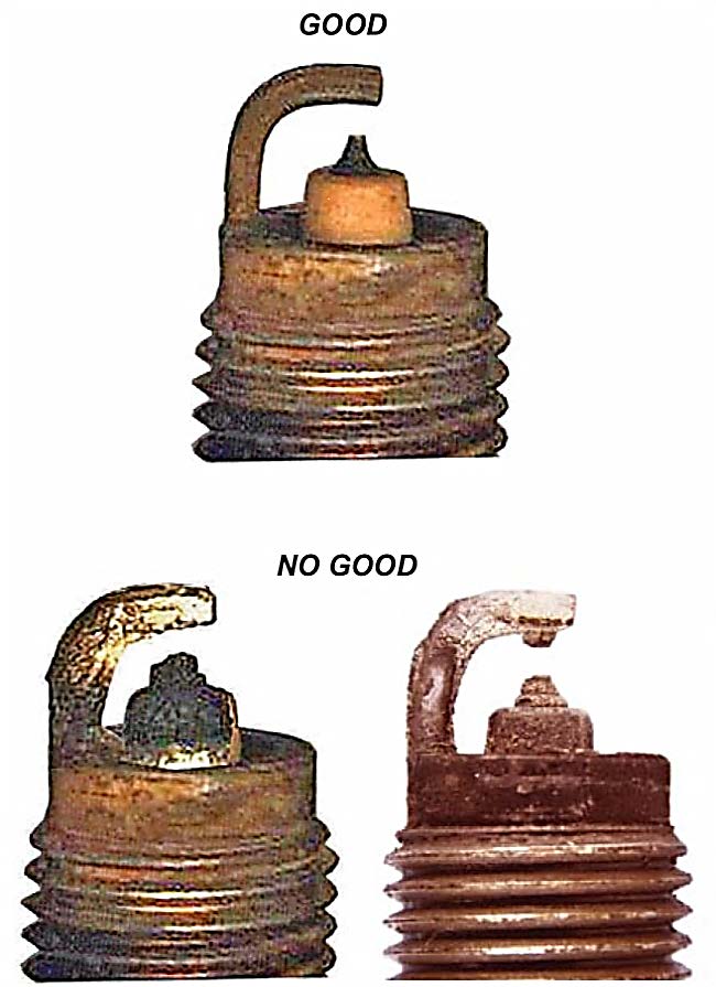
- Remove and check the spark plug(s) on the affected cylinders (example: if P0301 is stored, check the spark plug on cylinder No. 1).
Are the spark plug(s) fouled?
YES – Go to step 3.
NO – Stop. This bulletin does not apply. Continue with normal troubleshooting.
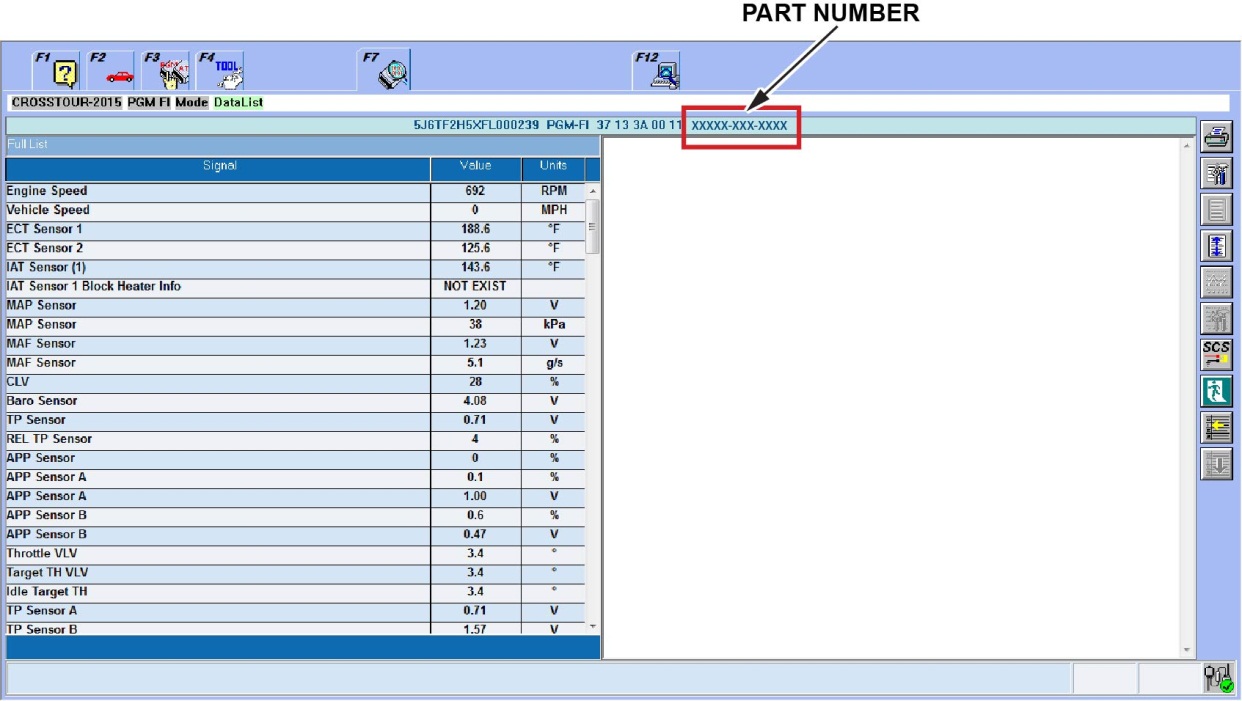
- Check the PCM software version P/N located above the PGM FI Data List. All 2012–13 vehicles are up to date, go directly to step 4.
| Year/Model | Program ID (or later) | Program P/N (or later) |
| 2009–10 Pilot (2WD) | N0A570 | 37805-RN0-A57 |
| 2009–10 Pilot (4WD) | N0A770 | 37805-RN0-A77 |
| 2011 Pilot (2WD) | N0A630 | 37805-RN0-A63 |
| 2011 Pilot (4WD) | N0A830 | 37805-RN0-A83 |
| 2012–13 Pilot (ALL) | Software Updated from Factory | |
Is the PCM Program ID and/or Program P/N the same or newer than what is listed above, 2009–11 model years only?
NO – The PCM software needs to be updated. Go to REPAIR PROCEDURE A.
YES – The correct software is installed. The piston rings on select cylinders need to be replaced. Go to step 4.
IMPORTANT NOTICE: The PCM software must first be updated with the correct version, replace spark plugs and the vehicle returned to the customer. Piston cleaning and piston ring replacement, as described below, should only be done after the customer has returned with a second failure or if the vehicle’s software is the correct version. Failure to follow this process correctly may result in a full debit of the warranty claim to your dealer.
- Note which DTCs are stored in the vehicle.
Does the vehicle have DTC P0304 stored? (Any combination of DTCs P0301, P0302, P0303, P0304 may also be stored.)
YES – Go to REPAIR PROCEDURE B for the cylinders listed, Cylinders 1–4: Clean the pistons, replace the piston rings, and replace the spark plugs.
NO – Go to REPAIR PROCEDURE B for the cylinders listed below:
- Cylinder 1–3: Clean the pistons and replace the pistons rings.
- Cylinder 1–4: Replace the spark plugs.
PARTS INFORMATION
NOTE: Do the DIAGNOSIS first to determine which cylinders you will need to repair.
REPAIR PROCEDURE A – SOFTWARE UPDATE AND CYLINDERS 1–4 SPARK PLUG REPLACEMENT
Required Parts
| Part Name | Part Number | Quantity |
| Spark Plugs (2009–11 All) | 12290-R70-A01
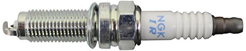
Genuine Honda 12290-R70-A01 Spark Plug
| 4 |
| Spark plugs (2012–13 All) | 12290-R71-L01

Genuine Honda 12290-R71-L01 Spark Plug (Dilzkr7A11G) (Ngk)
| 4 |
REPAIR PROCEDURE B – PISTON CLEANING AND RING REPLACEMENT Required Parts
| Part Name | Part Number | Cyl 1-3 | Cyl 1-4 |
| Cyl. Gasket (Fr Cylinder Head) | 12251-R70-A01
Genuine Honda 12251-R70-A01 Cylinder Head Gasket
| 1 | |
| Cyl. Gasket (Rr Cylinder Head) | 12261-R70-A01 | 1 | 1 |
| Drain Washer 14 mm | 94109-14000

Honda 94109-14000 Oil Drain Plug Gasket Pack of 50
| 1 | 1 |
| EGR Pipe Gasket A | 18716-R70-A01
Genuine Honda 18716-R70-A01 EGR Pipe Gasket A
| 1 | 1 |
| EGR Pipe Gasket B | 18719-R70-A01
Genuine Honda 18719-R70-A01 EGR Pipe Gasket B
| 1 | 1 |
| Ex. Chamber Gasket | 18115-R70-A01
Genuine Honda 18115-R70-A01 Exhaust Chamber (Nippon Leakless) Gasket
| 1 | 2 |
| Ex. Pipe Gasket | 18212-SA7-003
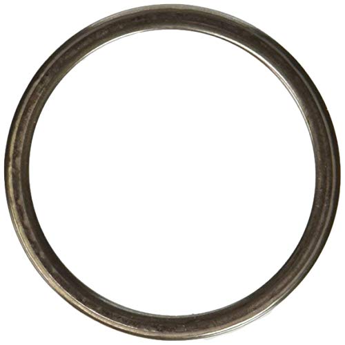
Genuine Honda 18212-SA7-003 Exhaust Pipe Gasket
| 2 | 2 |
| Head Gasket Fr (Valve Cover) | 12030-R70-A00

Genuine Honda 12030-R70-A00 Head Cover Gasket Set
| 1 | |
| Head Gasket Rr. (Valve Cover) | 12050-R70-A00
Genuine Honda 12050-R70-A00 Rear Head Cover Gasket Set
| 1 | 1 |
| In. Manifold Gasket (Intake Top Cover) | 17146-R70-A01

Genuine Honda 17146-R70-A01 Intake Manifold Gasket
| 1 | 1 |
| In. Manifold Gasket (2009–10 2WD) | 17105-RCA-A01
Sale
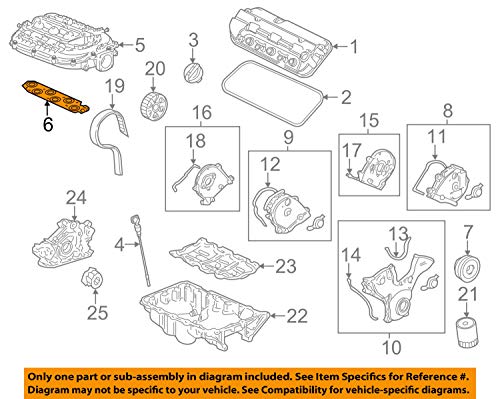
Genuine Honda (17105-RCA-A01) Intake Manifold Gasket
| 1 | 1 |
| In. Manifold Gasket (2009–13 4WD & 2011–13 2WD) | 17105-RCJ-A01

Genuine Honda (17105-RCJ-A01) Intake Manifold Gasket
| 1 | 1 |
| Oil Filter | 15400-PLM-A02
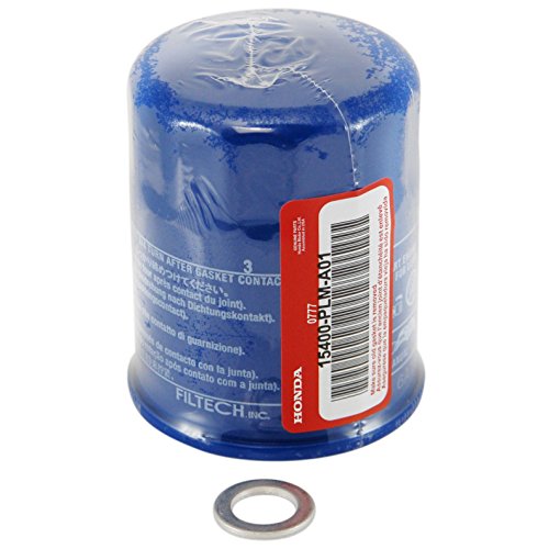
Honda 15400-PLM-A01 Oil Filter w/Washer
| 1 | 1 |
| O-ring (7.47 mm x 3.6 mm) | 91301-PLC-000

Honda Genuine O-Ring (7-47X3-6)
| 2 | 2 |
| O-ring (31.2 mm x 4.1 mm) | 91314-PH7-003
No products found. | 2 | 2 |
| Piston Ring Set | 13011-5G0-A02
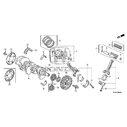
Genuine Honda Parts - Ring Set (Std) (13011-5G0-A02)
| 3 | 4 |
| Pre-chamber Gasket | 18393-SDB-A00
Genuine Honda 18393-SDB-A00 Pre Chamber Gasket
| 1 | 1 |
| Self-locking Nut (8 mm) | 90212-RCA-A01
Honda Genuine NUT, SELF-Lock (8MM)
| 4 | 8 |
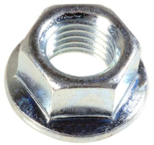
| Self-locking Nut (10 mm) | 90212–SA5-003 | 9 | 9 |
| Spark Plug (2009–11 All) | 12290-R70-A01
Genuine Honda 12290-R70-A01 Spark Plug
| 4 | 4 |
| Spark plug (2012–13 All) | 12290-R71-L01
Genuine Honda 12290-R71-L01 Spark Plug (Dilzkr7A11G) (Ngk)
| 4 | 4 |
| Strainer O-ring | 15221-RYE-A01
Honda Genuine O-Ring
| 1 | 1 |
| Timing Belt Bolt | 14551-RCA-A01
Genuine Honda 14551-RCA-A01 Timing Belt Idler Bolt
| 1 | 1 |
| Water Gasket Fr. | 19411-P8A-A03
No products found. | 1 | 1 |
| Water Gasket Rr. | 19412–P8A-A02
Honda Genuine Gasket, RR-
| 1 | 1 |
Replaced Parts as Needed for Repair Procedure B
| Part Name | Part Number | Cyl 1-3 | Cyl 1-4 |
| Connecting Rod Bolt (May require Up to 6 bolts per cylinder head) | 13204–P8A–A01
Honda 13204-P8A-A01 Bolt Connecting Rod
| 6 | 8 |
| Washer-Bolt (12 x 163) (May require up to 8 bolts per cylinder head) | 90005–PAA–A01

Genuine Honda 90005-PAA-A01 Bolt and Washer, Regular
| 8 | 16 |
REQUIRED MATERIALS – REPAIR PROCEDURE B
| Material Description | Part Number | Quantity |
| Honda Long-Life Antifreeze/Coolant Type 2 | OL999–9011
Sale

Honda Genuine Extended Life Antifreeze/Coolant Type 2, 50/50 Pre-Diluted, 1 Gallon
| 3 gallons |
| Genuine Honda Motor Oil 0W–20 | 08798–9036
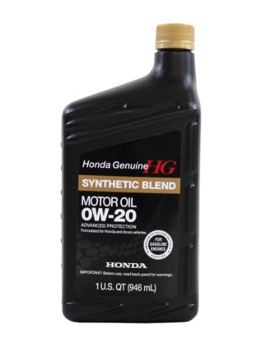
Genuine Honda Parts 08798-9036 0W-20 Blended Synthetic Motor Oil - 1 Quart
| 6 quarts |
| Genuine Honda Motor Oil 5W–20 (if requested) (2009-11) | 08798–9032

Genuine Honda 08798-9032 Synthetic Blend Oil 5W-20
| 6 quarts |
| Hondabond HT (1 Tube Repairs 5 Vehicles) | 08718–0004 | 1 tube |
| Genuine Honda Throttle Plate Cleaner | 08700–9204
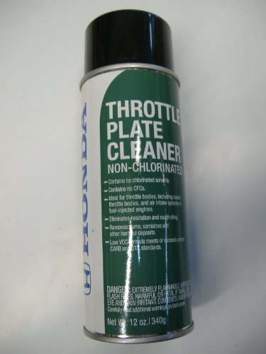
Honda 08700-9204 Throttle Plate Cleaner (Aerosol), 12 oz, 1 Pack
| |
| Nylon Parts Cleaning Brush | (commercially available) | |
| 5/16 ID Flexible Hose | (commercially available) |
TOOL INFORMATION – REPAIR PROCEDURE B
| Tool Description | Tool Number | Quantity |
| Piston Ring Groove Cleaner | 07AAZ–TA5A100 | 1 |
REPAIR PROCEDURE A – SOFTWARE UDPATE AND CYLINDERS 1–4 SPARK PLUG REPLACEMENT
- For 2009–11 models only, update the PCM software. Refer to Service Bulletin 01-023, Updating Control Units/Modules.
- Replace spark plugs on cylinders 1–4, then return the vehicle to the customer.
REPAIR PROCEDURE B – PISTON CLEANING AND RING REPLACEMENT
2009–11 Models: Confirm PCM software is or has been updated with the correct version, spark plugs 1–4 have been replaced and the vehicle returned to the customer (Procedure A). Piston cleaning and piston ring replacement along with the spark plugs should only be done after customer has returned with a second failure or if the vehicles software is the correct version (Procedure B). Failure to follow this process correctly may result in a full debit of the warranty claim to your dealer.
2012–13 Models: Are equipped with updated software from the factory, no software update is needed. Piston cleaning and piston ring replacement along with the spark plugs should only be done after the diagnosis of the spark plugs has concluded that (Procedure B) is required.
The following service manual procedures have been used in full or in part within this service bulletin. For more detail on these procedures, and torque specifications for some components, refer to the appropriate electronic service manual.
- Battery Terminal Disconnection and Reconnection
- Fuel Pressure Relieving
- Fuel Line/Quick-Connect Fitting Removal
- Air Cleaner Removal/Installation
- Splash Shield Replacement
- Drive Belt Removal/Installation
- Engine Oil Replacement
- Coolant Replacement
- Hydraulic Power Steering Fluid Check/Replacement
- Intake Manifold Removal and Installation
- Timing Belt Removal and Installation
- Warm Up-TWC Removal/Installation
- Cylinder Head Cover Removal
- Cylinder Head Removal and Installation
- Piston Ring Replacement
- PCM Idle Learn Procedure
- Valve Adjustment
Piston Removal Procedure
- Use fender covers to avoid damaging painted surfaces.
- To avoid damaging any wires and terminals, unplug the circuit connectors carefully while holding the connector portion.
- Mark all the circuits and hoses to avoid misconnection. Make sure they do not contact other circuit wiring, hoses, or interfere with other parts.
- Relieve the fuel pressure.
- Remove both front wheels so you can fully lower the vehicle.
- Remove the intake duct.
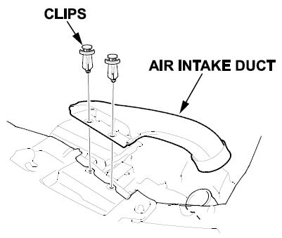
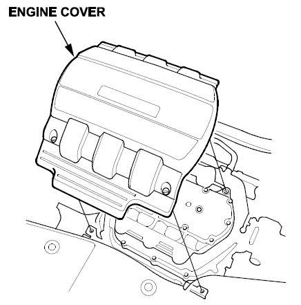
- Remove the engine cover.
- Remove the radiator cap.
- Raise the vehicle.
- Remove the front splash shield.
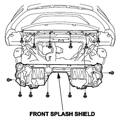
- Drain the engine oil.
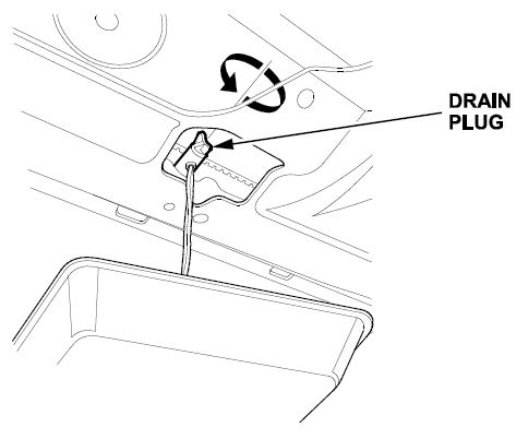
- Loosen the drain plug on the radiator, and drain the coolant.
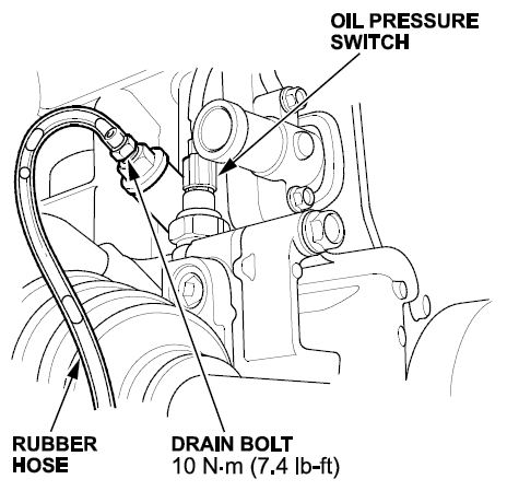
- Install a 5/16th inner diameter rubber hose on the drain bolt at the rear of the engine block, loosen the drain bolt, and drain all remaining coolant. Then disconnect the oil pressure switch connector.
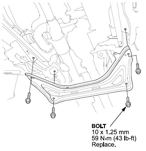
- Remove the subframe stiffener.
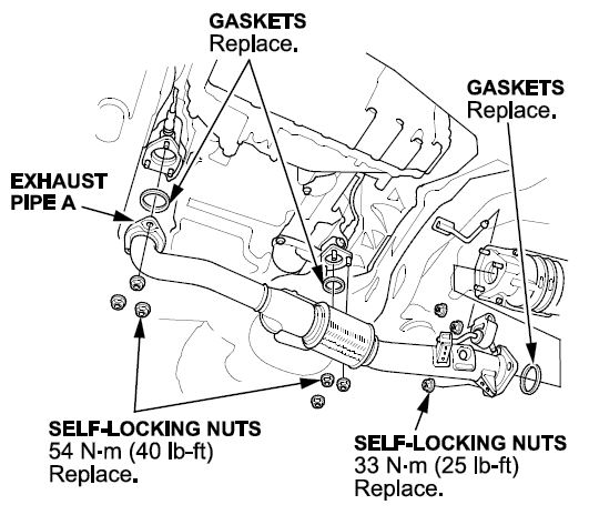
- Remove exhaust pipe A.
- Depending on the diagnosis, remove the appropriate WU-TWC support bracket bolts.
- Remove the EGR lower pipe nuts.
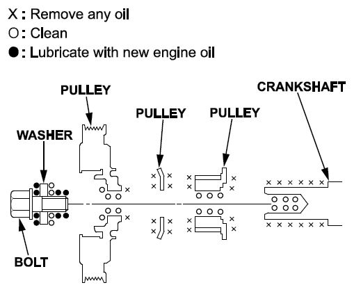
- Remove the crankshaft pulley bolt but not the pulley.
NOTE: Make sure to apply new oil to the bolt flange and threads before reinstallation.
- Lower the vehicle.
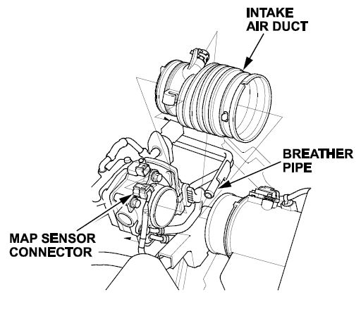
- Disconnect the MAP sensor connector and the breather pipe, then remove the intake air duct.
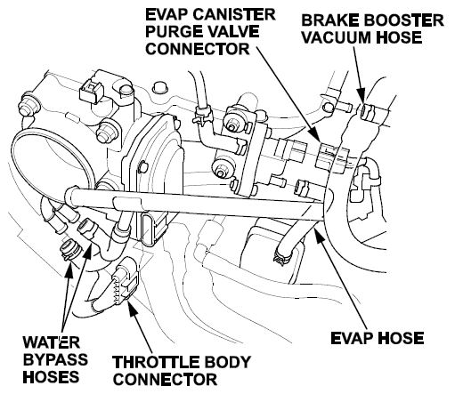
- Disconnect the throttle body connector, the EVAP canister purge valve connector, the EVAP hose, the brake booster vacuum hose, and the vacuum hose.
- Disconnect and plug the water bypass hoses.
- Remove the drive belt.
- Remove the drive belt auto-tensioner.
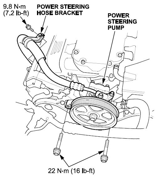
- Remove the power steering pump bolts, the power steering bracket then secure the power steering pump out of the way.
NOTE: Do not remove any of the hoses.
- Remove the engine harness holder bolt on the side engine mount.
- Set the engine to TDC cylinder one.
- Remove the crankshaft pulley.
- Remove the timing belt.
- Remove the timing belt idler pulley.
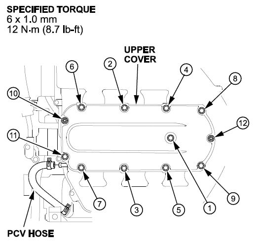
- Remove the engine intake upper cover bolts and nuts. Then remove the cover and the PCV hose.
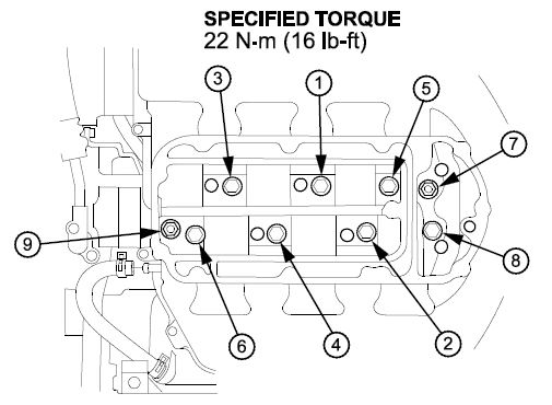
- Remove the intake manifold bolts and nuts in three steps, then remove the intake manifold.
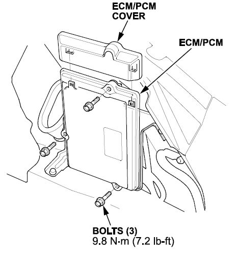
- Remove the PCM cover and connectors. Disconnect the battery cables from the underhood fuse box.
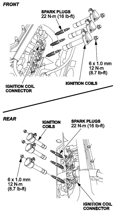
- Remove the appropriate Ignition coils based on the diagnosis.
NOTE: Depending on the diagnosis, you will either have to remove the rear bank ignition coils or both ignition coil banks.
- Depending on the diagnosis, remove some or all of the following components:
- ECT sensor connector
- Front rocker arm oil pressure switch connector
- Rear rocker arm oil pressure switch connector
- CMP sensor connector
- Front A/F sensor one connector
- Rear A/F sensor one connector
- Front secondary HO2S connector
- Rear secondary HO2S connector
- Rocker arm oil control solenoid A connector (bank one) Rocker arm oil control solenoid A connector (bank two)
- Rocker arm oil control solenoid B connector (bank one)
- Alternator connector and positive alternator cable
- A/C clutch switch connector
- EGR 5P valve connector
- Engine ground
- Knock sensor
- Fuel injector connectors and clips
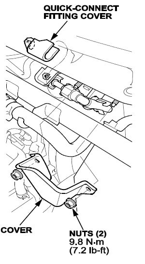
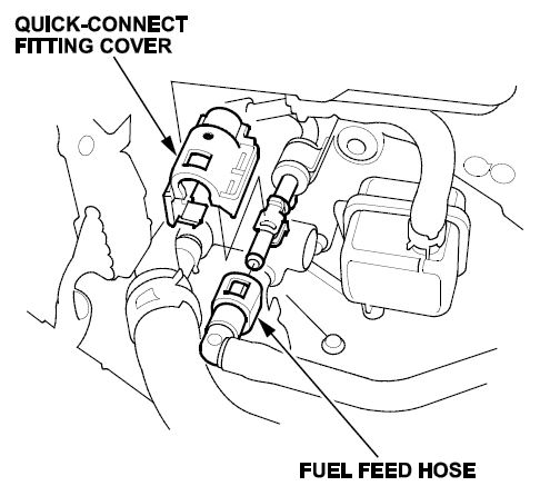
- Remove the quick-connect fitting cover, then disconnect the fuel feed hose.
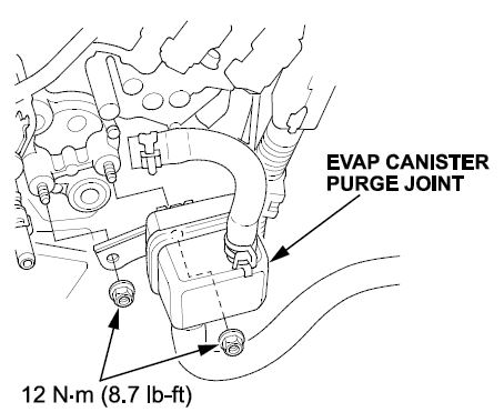
- Remove the EVAP canister purge joint with the bracket.
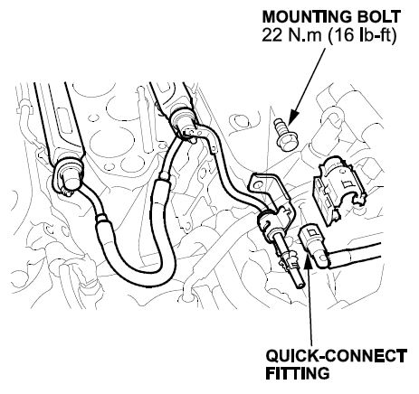
- Remove the fuel rail connecting joint hose.
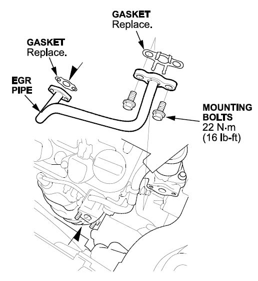
- Remove the EGR pipe mounting bolts, then remove the EGR pipe.
- Separate the water passage from the heads.
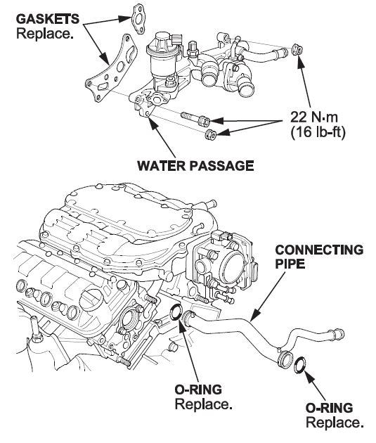
- Remove the appropriate WU-TWC depending on diagnosis.
NOTE: Set the WU-TWC aside and cover the opening with shop towels to prevent coolant from entering.
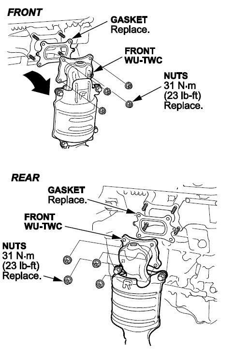
- Remove the appropriate head with the injector base attached.
NOTE: Depending on diagnosis, you will remove the rear bank head or both heads.
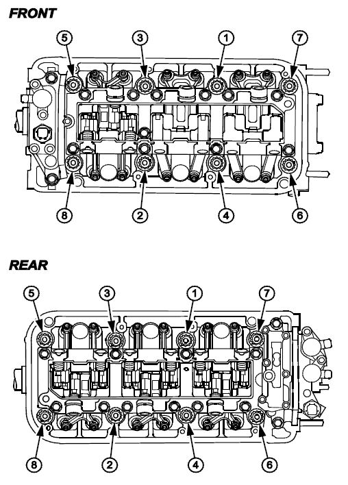
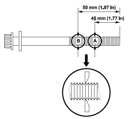
- Measure the head bolts to determine if they need replacement. If either diameter is less than 3 mm (0.445 in), replace the cylinder head bolt.
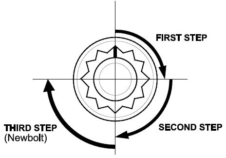
NOTE: Torque the bolts using the following steps for reinstallation.
- First step: torque the cylinder bolts in sequence to 29 N•m (22 lb-ft).
- Second step: tighten in sequence an additional 90 degrees.
- Third step: tighten in sequence an additional 90 degrees.
- If the bolts are new, tighten an additional 90 degrees.
- Raise the vehicle.
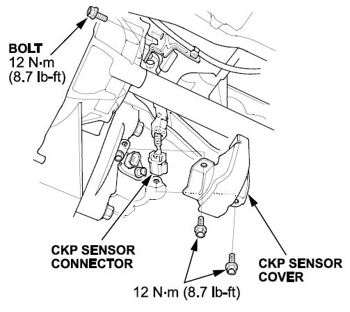
- Remove the CKP sensor cover and bolts, then disconnect the CKP sensor connector.
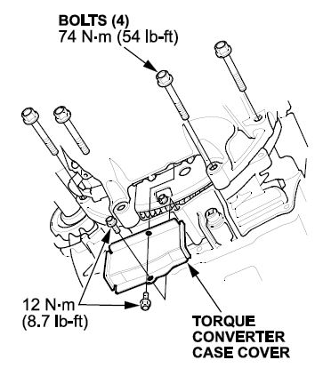
- Remove the torque converter case cover and the four bolts securing the oil pan to the transmission.
- Remove all bolts securing the oil pan.
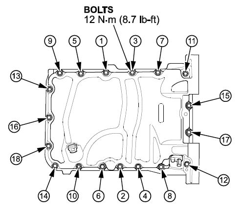
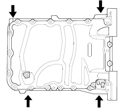
- Using a flat blade screwdriver, separate the oil pan from the engine block in the areas shown.
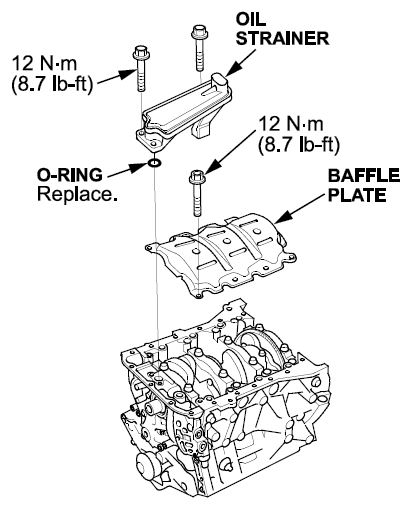
- Remove the oil strainer and baffle plate.
- Lower the vehicle to a comfortable working height, and place a clean shop towel around the cylinder wall to prevent debris from entering the coolant passage.
- Remove the appropriate piston depending on diagnosis, then go to PISTON CLEANING PROCEDURE.
NOTE: When removing the piston rod caps, be sure and keep all caps and bolts with their corresponding pistons for reassembly purpose.
Piston Cleaning and Ring Replacement Procedure
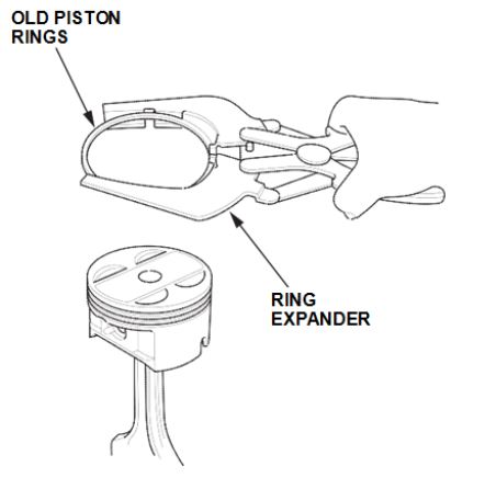
- Remove the piston rings from the piston using a ring expander. Be careful not to damage the piston.
- Spray the piston head and piston ring grooves thoroughly with Honda throttle plate cleaner.
- While holding the piston upright in your left hand, take the piston ring groove cleaner tool in your right hand and line up the cleaner tool guides with the second (middle) piston ring groove.
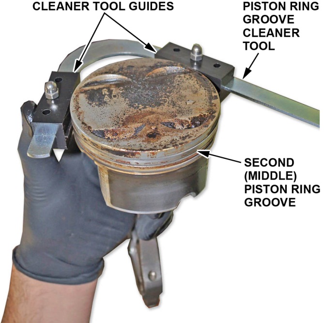
- Press the handle on the piston ring groove cleaner tool and slide the cleaning bit onto the appropriate piston ring grooves.
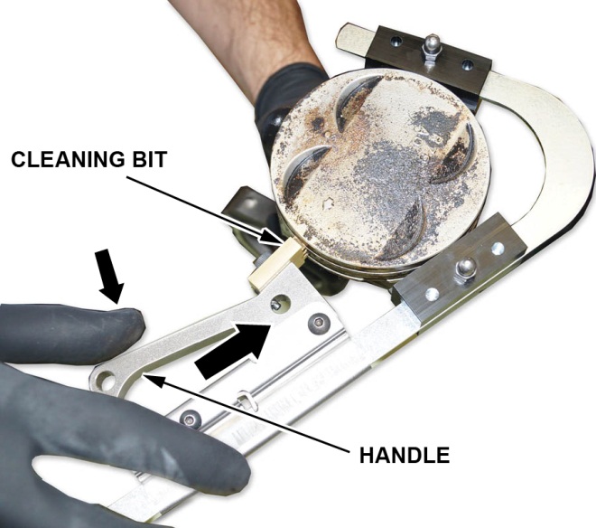
- Once the cleaning bit is in the appropriate ring grooves of the piston, make sure the tool handle clicks into place.
NOTE: There is only one notch on the tool for the handle to engage.
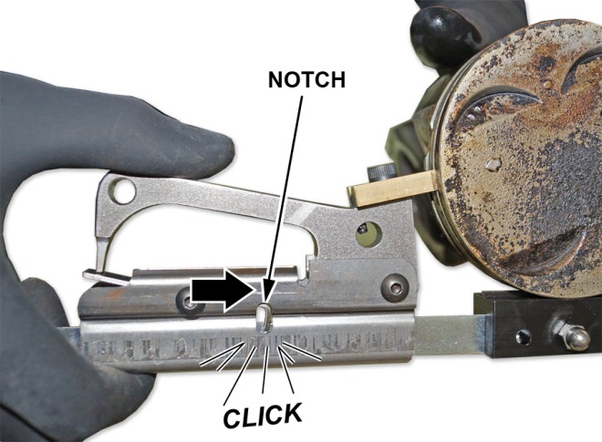
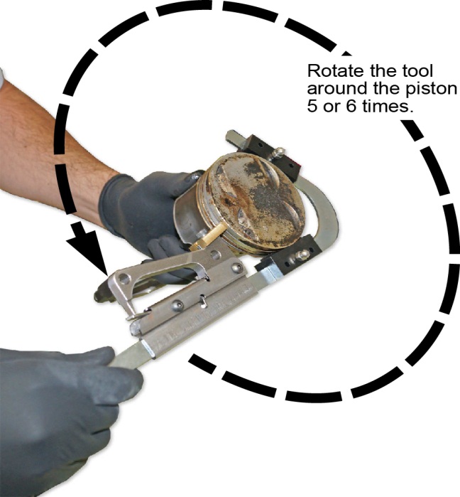
- Hold the piston steady and rotate the tool counter-clockwise five to six times to remove any carbon deposits in the piston ring grooves. Do not rotate the tool clockwise.
NOTE: You can watch this procedure in the Tech2Tech segment “How to Clean Piston Ring Grooves”.
- Remove the piston groove cleaning tool and clean off the carbon from the tool bit.
- Finish cleaning the piston with throttle plate cleaner and the nylon brush. Do not use a steel wire brush.
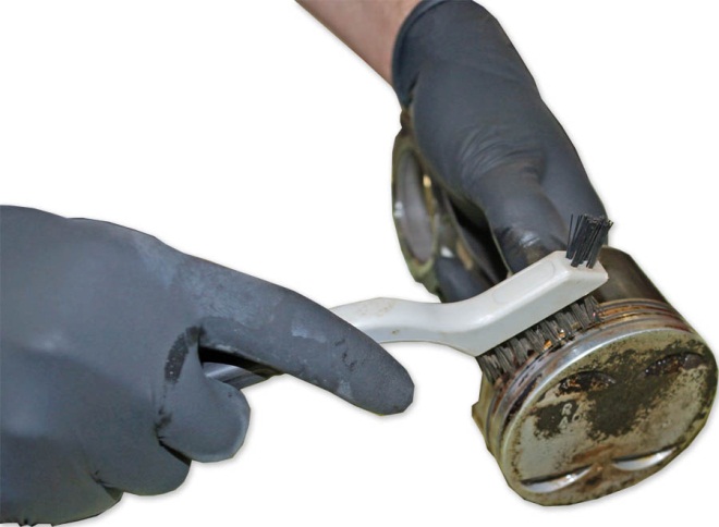
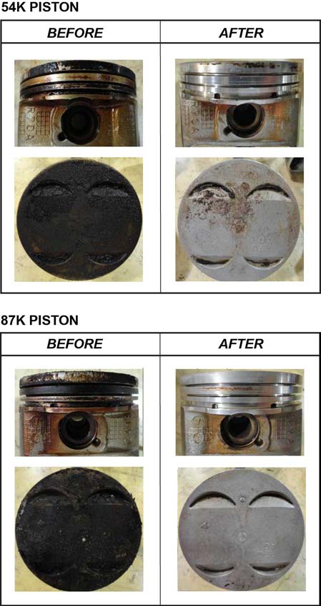
NOTE: Below are some examples of before and after pictures. Depending on mileage and running conditions, the pistons will achieve different levels of cleanliness.
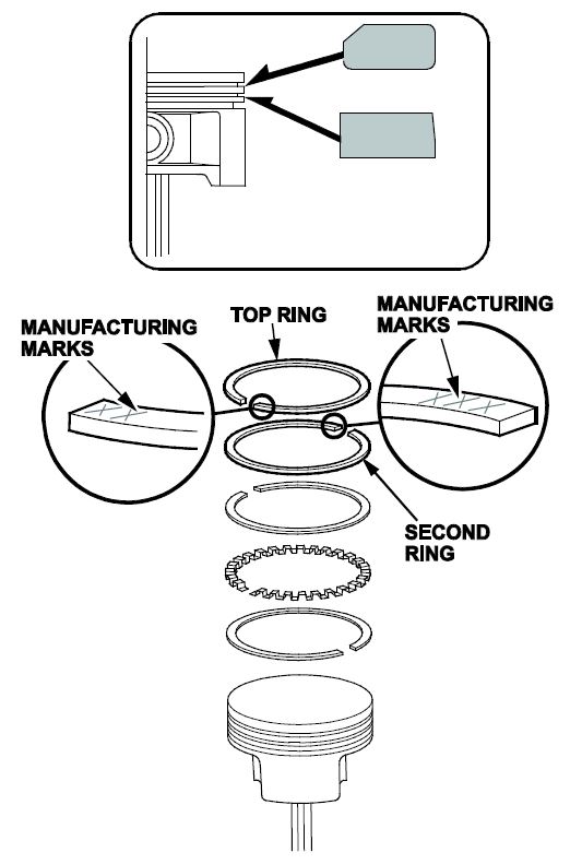
- Install the piston rings as shown.
NOTE: The first (top) ring has a 1D manufacturing mark and the second (middle) ring has an SPR manufacturing mark.
The manufacturing marks must be facing upward.
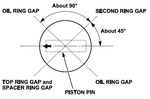
- Position the ring end gaps as shown.
NOTE: If the ring gaps are not positioned correctly, excessive blowby may occur.
- Apply new engine oil to the piston, the inside of the piston ring compressor, and the cylinder bore.
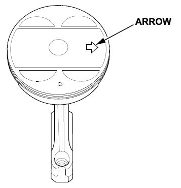
- Install the piston/connecting rod assembly into the cylinder bore with the arrow on top of the piston facing the timing belt side of the engine.
NOTE: Be careful not to damage the cylinder wall when installing the piston.
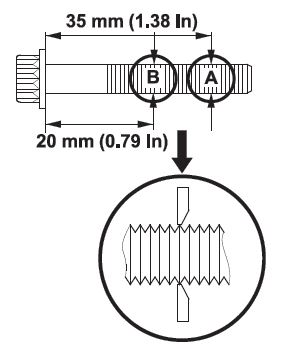
- Measure the diameter of the connecting rod bolts to determine if they need replacement. Calculate the difference in diameter between point A and point B. It should not be more than 0–0.1 mm (0–0.004 in).
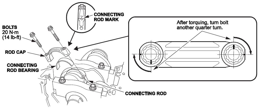
- Apply new oil to the connecting rod bolt threads and flanges. Torque the bolts to 20 N•m (14 lb-ft) then tighten the connecting rod bolts an additional 90 degrees.
- Reinstall the remaining components in the reverse order of removal.
- Replace spark plugs 1–4.
- Replace the oil filter and refill all fluids.
- Do the idle learn procedure.
END.
5 Affected Products
Vehicle
| MAKE | MODEL | YEAR |
| HONDA | PILOT | 2009-2013 |
1 Associated Document
Service Bulletin Document
A13-082
May 18, 2015
51869-02164 Version 7
SB-10083965-2280.pdf 2670.231KB
Reprogramming
i-HDS Diagnostic Software and J2534 Reprogramming Software
Honda J2534 Pass-Thru User Guide
Honda J2534 Pass-Thru Software Download
i-HDS Diagnostic Software and J2534 Reprogramming Software
American Honda Motor Co., Inc. ("Honda") offers the i-HDS (Honda Diagnostic System) software suite for the diagnosis and repair of electronic systems on Honda and Acura automobiles, and for the reprogramming of electronic control units (including, but not limited to, ECMs and PCMs). This software provides access to all Honda and Acura vehicle systems (access to the immobilizer security system requires a Security Professional level software subscription and Vehicle Security Professional [VSP] registration with NASTF). To use the i-HDS software, you need to purchase one of our convenient subscription options. In addition, you will need a pass-thru Vehicle Communication Device (VCI) that is compliant with SAE J2534-1 and J2534-2 in order to communicate with the vehicle
Vehicle Communication Interfaces (VCI)
The i-HDS software supports the use of a generic pass-thru VCI that is compliant with SAE J2534-1 and J2534-2. However, Honda recommends the Denso DST-i or the Bosch MVCI for use on Honda and Acura vehicles, as Honda has worked closely with these manufacturers to ensure their hardware and our software interact safely and within the J2534-1 and -2 specifications, for both diagnostics and reprogramming. If you choose to use a generic VCI, please carefully consider the customer and technical support options you will receive from your chosen device supplier. Honda does not provide technical or customer support for generic VCI devices.
The VCI Application Table below lists devices that either are approved and supported by Honda or are known to have completed and passed an independent, exhaustive validation program with our i-HDS software suite.
| VCI Name | Manufacturer | Version Information | Notes | |
|---|---|---|---|---|
| Firmware | J2534 API | |||
| DST-i | DENSO | 2.02.0002* | 04.04 | This is the current generation VCI used by Honda and Acura dealers. Honda routinely validates the functionality and provides customer support for this device. |
| DST-nano | DENSO | 2.02.0002* | 04.04 | This is the current generation VCI used by Honda Canada Inc. Honda and Acura dealers. Honda routinely validates the functionality and provides customer support for this device. |
| MVCI | Bosch | 3.01.60* | 04.04 | This is the previous generation VCI used by Honda and Acura dealers. Honda routinely validates the functionality and provides customer support for this device. |
| MongoosePro Honda | Drew Technologies | 1.9.5** | 04.04 | This company has completed an independent i-HDS validation and claims it to function with the i-HDS software. Honda does not provide ongoing validation, nor customer support for this device. |
| d-briDGe Pro | Dearborn Group | 3.303** | 04.04 | This company has completed an independent i-HDS validation and claims it to function with the i-HDS software. Honda does not provide ongoing validation, nor customer support for this device. |
* These versions may have been superseded. Honda provides the latest supported versions to current i-HDS subscribers.
** Version used in validation program. See Terms and Conditions and Important Notice Regarding Reprogramming below for more details.
Reprogramming with the J2534 Rewrite Application in i-HDS
Included in the i-HDS software suite is a new reprogramming application called J2534 Rewrite. This application is made available to all subscribers of the i-HDS software suite and replaces the previous generation software, J2534 Honda Pass-thru Reprogramming Software.
This new application is compatible with generic VCIs that comply with SAE J2534. It must be used to reprogram any Honda/Acura vehicle equipped with ECUs that support reprogramming. Refer to the table below for legacy applicability for the programming of ECMs and PCMs. Though system dependent, late-model vehicles may be equipped with other ECUs that support reprogramming as well, e.g. ABS or VSA. J2534 Rewrite must be used to reprogram these control modules, as instructed in an applicable service bulletin.
As shown in this table, not all legacy Honda/Acura models are equipped with a reprogrammable ECM/PCM. Furthermore, all 2007 and later models not listed in the table are fully supported with this application.
DST-i Information:
MVCI Information:

- J2534 Pass-Thru Programmer: TOPDON RLink J2534 is an advanced diagnostic and reprogramming tool that support all J2534 protocols, as well as D-PDU, CAN-FD and DoIP, ensuring compatibility with a wide range of modern vehicles. It offers extensive versatility with support for over 18 major automotive brands, including Chrysler, Ford, GM, Nissan, Toyota, Honda, Subaru, Land Rover/Jaguar, Volvo, Wuling, Volkswagen/Audi, Mercedes-Benz, and BMW. NOTE: Not compatible with Ford IDS diagnostic software
- All-in-One OEM Diagnostics: This J2534 ECU programming tool elevates your automotive repair capabilities to new heights by delivering complete OEM diagnosis. Boasting comprehensive full-system diagnostics, intuitive repair guides, advanced ECU programming and coding, common reset services, a vast library of repair information and more, this all-in-one solution empowers technicians to effortlessly tackle complex vehicle issues with ease. *Not compatible with 24V vehicles
- Proven Performance You Can Trust: Backed by over 10000 real vehicle tests and benefit from a wealth of practical experience, this OEM reprogramming tool guarantees stable and exceptional performance. Supported by TOPDON's dedicated technical experts with in-depth knowledge of both auto repair and J2534 Pass-Thru programming, the RLink J2534 provides prompt and professional assistance, ensuring a smooth setup and reliable compatibility
- Integrated Excellence, Always Up-to-Date: Featuring the exclusive RLink Platform to provide a streamlined experience with one-click driver installation and management, ensuring flawless integration with your OE software, maintaining the original performance quality. The built-in operation guide makes mastering OE software quick and easy, so you can get started right away. Plus, with lifetime free updates, your diagnostics will stay current with the latest drivers and innovations
- Efficiency Meets Versatility: Engineered to support three CAN channels simultaneously - CAN FD and CAN-CC included, giving you the edge in fast troubleshooting. To perfectly synchronized with the OE software, please diagnose with active subscriptions and make sure your computer system is running a compatible 64-bit Windows version (7, 8, 10 or later) to fully leverage the power of RLink J2534. *We don't provide extra OE software

- Advanced VCI Box, Industry-leading J2534 Pass-Thru Technology: This J2534 Pass-Thru Programmer is designed espically for technicians, independent shop owners, and DIY enthusiasts, enables fast, reliable computer-based programming. It supports all J2534 protocols—including the latest DoIP and CAN FD—ensuring full compatibility with both legacy and next-generation vehicles.
- High-Speed OEM-Level Diagnostics & Programming: Unlock true OEM functionality with comprehensive system diagnostics, guided troubleshooting, coding, adaptations, resets, and programming—all designed to slash repair time. This all-in-one tool eliminates the need for multiple OEM devices, boosting efficiency and cutting costs. Equipped with High-Speed USB, it delivers 10x more data per second than competing solutions
- Coverage for 17 Car Brands & Ultra Reliability: Works seamlessly for Chrysler, for Ford(Forscan), for GM, for Nissan, for Toyota, for Honda, for Subaru(SSM4), for Land Rover/Jaguar, for Volvo, for Wuling, for Volkswagen, for Mercedes-Benz, and for BMW. Backed by over 10000 real vehicle tests and benefit from a wealth of practical experience, this OEM reprogramming tool guarantees stable and exceptional performance
- User-Friendly RLink Platform & Expert Support: TOPDON’s proprietary driver management platform offers a clean interface and lifetime free updates. Access a rich library of real-world case studies to stay ahead of the curve. Backed by a support team with 10+ years of J2534 and automotive repair experience, we provide one-on-one assistance to resolve any technical issue.
- 6.6 ft USB-C Cable & Portable Storage Case: The RLink J2534 diagnostic tool features a 6.6ft USB 2.0 Cable and a 1.2 ft OBDII Extension Cable, allows to connection your computer easily outside the vehicle. The included handled carry case offers easy portability, storage, and hanging options—keeping your gear clean and ready to go, anywhere.
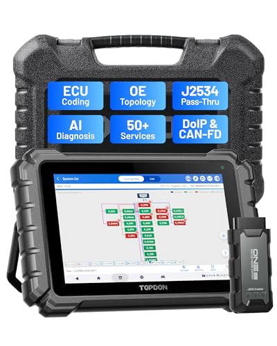
- Dual WiFi & 10.1" Touchscreen: Provides a stable, high-speed wireless link 3x faster than bluetooth, and a responsive, professional interface. Topdon ONE obd2 scanner diagnostic tool ensures smooth, non-lagging diagnostic scan, boosting mechanic efficiency
- J2534 Pass-Thru Support: The included ONE VCI supports the J2534 standard, allowing it to function as a pass-thru device when paired with OEM diagnostic software.Through TOPDON’s RLink platform, technicians can perform dealer-level coding, expanding in-house capabilities without investing in multiple factory automotive scan tools
- OE Topology Mapping: Visualize the vehicle’s ECU network exactly as it’s built.Zoom, pan, and highlight specific modules to pinpoint component issues with precision.Topology mapping displays real-time communication between modules
- 50+ Service Functions: Covers high-demand services like ADAS calibration, DPF regen, TPMS reset, ABS bleed, and throttle adaptation.Expands your service menu, allows you to charge premium rates, and turns away zero jobs due to lack of tooling. Vehicle-specific functionality may vary
- Advaned ECU Coding: 10 of the most serviced brands in North America, including full ECU coding and flash hidden support for BMW, VW, Au-di, Benz, Porsche, Toyota, Ni ssan and more. Enables module replacement, feature customization, and personal settings with automatic backup or restore.Lets your shop safely offer high-margin customization services, attracting more customers and boosting profit

- [J2534 Pass-Thru Programmer] - TOPDON RLink J2534 is engineered for professional technicians, delivering OEM diagnostic and reprogramming capabilities. It supports all J2534 protocols, CAN-FD, DoIP, D-PDU. Compatible with 17 vehicle brands—such as Chrysler, Ford, GM, KIA, Hyundai, Nissan, Toyota, Honda, Subaru, Mitsubishi, MAZDA, Land Rover/Jaguar, Volvo, Volkswagen/Audi, Mercedes-Benz, and BMW. RLink J2534 can help reduce the cost of purchasing equipment from different brands.
- [All-in-One OEM Reprogramming and Diagnostics] - When seamlessly integrated with OEM diagnostic software, this dongle enables you to perform a wide range of functions, including ECU programming and coding, DTC reading and clearing, active tests, component matching, adaptations, rewriting, guided troubleshooting, and more. This all-in-one tool eliminates the need for multiple OEM devices, significantly boosting work efficiency.
- [Tested, Trusted, and Proven for Accuracy] - TOPDON RLink J2534 is renowned for its reliability, having successfully completed over 10,000 real-vehicle tests. The wealth of data and hands-on experience behind it ensures consistent performance and accurate results. You can trust this tool to deliver optimal performance.
- [One-Click Installation, Continuous Updates] - The exclusive TOPDON RLink platform streamlines installation with a one-click driver setup, allowing you to quickly access OEM software for diagnostic and reprogramming tasks. With lifetime free updates, your RLink J2534 stays current without any additional cost, ensuring reliable performance for the long term. *We don't provide extra OE software.
- [Works with Windows Compatibility and OEM Software Subscription] - The RLink J2534 supports three CAN channels - including CAN FD and CAN-CC, providing advantages in the process of rapid troubleshooting. Compatible with Windows 7, 8 and 10 (64-bit) and higher versions of the system. For full functionality, an active OEM software subscription is required for each supported vehicle brand. Please note that the dongle does not include OEM software, which must be purchased separately to access brand-specific diagnostic and reprogramming features.

- 【J2534 Pass-Thru Device】 This budget-friendly J2534 pass-thru device delivers OEM diagnostics and reprogramming capabilities for dealerships, repair shops and automotive DIY enthuisasts, enables you diagnose, program and repair the vehicles more efficiently and precisely. Supporting J2534, D-PDU, CAN-FD and DoIP, this J2534 passthru tool ensures wide vehicle coverage. It's compatible with OE software application, ensuring seamless integration and original performance quality
- 【All-in-One Diagnostic Tool】 Simplify your workflow and tackle the complex diagnostics and repairs with confidence! This J2534 passthrough tool provides full system diagnosis, bi-directional control, maintenance reset services, ECU programming and ECU coding to run advanced diagnostics and programming. Equipped with the specialized platform, this J2534 pass-thru tool is fully compatible with OE software that helps technicians confidently handle complicated vehicle repair issues
- 【J2534 Diagnostic Tool】 The Tabscan J2534 pass-thru device is built with a dedicated platform, making it ideal for both professional and personal use. Simply download the driver for your ford vehicle within the platform—ensuring only one driver is installed at a time. Then connect the device to your vehicle’s OBD2 port and link it to your computer using the included USB A to USB C cable. Finally launch your OE software, select Tabscan J2534 VCI as interface, and begin diagnose and program
- 【Universal Compatibility】 Tabscan J2534 reprogramming tool is designed to be compatible with Ford vehicles for advanced diagnostics and programming. It supports J2534 protocols, along with D-PDU, CAN-FD and DoIP, ensuring seamless connectivity with older or modern vehicles. This J2534 diagnostic tool only works with computer running on windows 7/10/11. Vehicle compatibility varies by model or year, please confirm with us before purchase. Note: It's not compatible with 24V vehicles
- 【Professional Technical Support】 Tabscan J2534 pass-thru device provides a stable and seamless connection between your vehicle and computer for diagnostics, programming, and coding. But that's not all—we go beyond hardware. Our dedicated technical support team brings deep expertise in automotive diagnostics and programming. Whether you need help with setup, troubleshooting or latest diagnostic resources and upgrades, we provide fast, professional and reliable support every step of the way

- ALL OF THE J2534 PROTOCOLS - This single unit has all of the protocols you need for your OEM J2534 reprogramming and diagnostics including the latest in DoIP and CanFD
- J2534 TECHNICAL SUPPORT - FREE for the life of the tool. Staffed by technicians who understand vehicle repair and J2534 Pass‑thru
- TOOLBOX WITH OEM APPLICATION DESCRIPTIONS - educational video tutorials and real-time news – Giving you the confidence and up-to-date knowledge to get the job done
- J2534 v05.00 API - The newest version of J2534 to give you the latest in pass-thru technology
- FUTURE PROOF WITH 4 CAN CHANNELS - Going beyond the 3 required by select Chrysler/FCA models, CarDAQ-Plus 3 also provides a 4th to meet the needs of future OEM applications
SEOCONTENT-START
CUSTOMER INFORMATION: The information in this bulletin is intended for use only by skilled technicians who have the proper tools, equipment,
and training to correctly and safely maintain your vehicle. These procedures should not be attempted by “do-it-yourselfers,” and you should not
assume this bulletin applies to your vehicle, or that your vehicle has the condition described. To determine whether this information applies, contact
an authorized Honda automobile dealer.
© 2016 American Honda Motor Co., Inc. – All Rights Reserved Page 1 of 24
Service Bulletin 13-082
May 18, 2015 51869-02164 Version 7
Warranty Extension: MIL Comes On With DTCs P0301 thru P0304
Supersedes 13-082, dated September 12, 2015, to revise the information highlighted in yellow.
AFFECTED VEHICLES
Year
Model
Trim
VIN Range
2009–13
Pilot
ALL
Check the iN VIN Status for Eligibility
REVISON SUMMARY
• Under REPAIR PROCEDURE B – PISTON CLEANING AND RING REPLACEMENT, Replace Parts as Needed for Repair Procedure B, changed bolt count for the 12 x 163 Washer bolt (P/N 90005-PAA-A01) under Cyl 1-4 from 8 to 16. Also changed the bolt count for Connecting Rod Bolt from 8 to 6.
CORRECTIVE ACTION
2009–11 Models: Complete the diagnosis procedure and if necessary, update the PCM software and replace the affected spark plugs. If the vehicle returns after the updated PCM software and spark plug replacement have been installed, clean the pistons and replace the pistons rings along with the spark plugs (Procedure B).
NOTE: Make sure the software update has been completed, spark plugs replaced (Procedure A), and the vehicle returned to the customer before making any additional repairs. Failure to do so will result in claim review by your DPSM and possible debit.
2012–13 Models: Complete the diagnosis procedure and if necessary, clean the pistons and replace the pistons rings along with the spark plugs (Procedure B).
BACKGROUND
American Honda is announcing a powertrain warranty extension as a result of a settlement of a class action captioned, Soto et al.v. American Honda Motor Co., Inc., Case No. 3:12-cv-1377-SI (N.D. Cal.).
The piston rings on certain cylinders may rotate and align, which can lead to spark plug fouling. This can set DTCs P0301 No. 1 cylinder misfire detected, P0302 No. 2 cylinder misfire detected, P0303 No. 3 cylinder misfire detected, P0304 No. 4 cylinder misfire detected, and cause the MIL to come on.
American Honda is extending the powertrain warranty to cover repairs related to engine misfire (that triggers DTCs P0301 through P0304) to 8 years with unlimited mileage from the original date of purchase and has settled a class action based on this remedial measure.
This warranty extension does not apply to any vehicle that has ever been declared a total loss or sold for salvage by a financial institution or insurer, or has a branded or similar title under any state’s law.
CUSTOMER NOTIFICATION
Owners of affected vehicles were sent a class action settlement notice regarding this warranty extension starting in October 2013.
Before doing work on a vehicle, verify its eligibility by doing an iN VIN status inquiry.
Refer customers seeking information about settlement benefits to www.enginemisfiresettlement.com, or instruct them to call 888-888-3082.
Page 2 of 24
DIAGNOSIS
1. Connect the HDS and check for the following DTCs: P0301 No. 1 Cylinder Misfire Detected, P0302 No. 2 Cylinder Misfire Detected, P0303 No. 3 Cylinder Misfire Detected, P0304 No. 4 Cylinder Misfire Detected.
Are any of these DTCs stored?
YES – Go to step 2.
NO – Stop. This bulletin does not apply. Continue with normal troubleshooting.
2. Remove and check the spark plug(s) on the affected cylinders (example: if P0301 is stored, check the spark plug on cylinder No. 1).
Are the spark plug(s) fouled?
YES – Go to step 3.
NO – Stop. This bulletin does not apply. Continue with normal troubleshooting.
Page 3 of 24
3. Check the PCM software version P/N located above the PGM FI Data List. All 2012–13 vehicles are up to date, go directly to step 4.
Year/Model
Program ID (or later)
Program P/N (or later)
2009–10 Pilot (2WD)
N0A570
37805-RN0-A57
2009–10 Pilot (4WD)
N0A770
37805-RN0-A77
2011 Pilot (2WD)
N0A630
37805-RN0-A63
2011 Pilot (4WD)
N0A830
37805-RN0-A83
2012–13 Pilot (ALL)
Software Updated from Factory
Is the PCM Program ID and/or Program P/N the same or newer than what is listed above, 2009–11 model years only?
NO – The PCM software needs to be updated. Go to REPAIR PROCEDURE A.
YES – The correct software is installed. The piston rings on select cylinders need to be replaced. Go to step 4.
IMPORTANT NOTICE: The PCM software must first be updated with the correct version, replace spark plugs and the vehicle returned to the customer. Piston cleaning and piston ring replacement, as described below, should only be done after the customer has returned with a second failure or if the vehicle’s software is the correct version. Failure to follow this process correctly may result in a full debit of the warranty claim to your dealer.
4. Note which DTCs are stored in the vehicle.
Does the vehicle have DTC P0304 stored? (Any combination of DTCs P0301, P0302, P0303, P0304 may also be stored.)
YES – Go to REPAIR PROCEDURE B for the cylinders listed, Cylinders 1–4: Clean the pistons, replace the piston rings, and replace the spark plugs.
NO – Go to REPAIR PROCEDURE B for the cylinders listed below:
• Cylinder 1–3: Clean the pistons and replace the pistons rings.
• Cylinder 1–4: Replace the spark plugs.
Page 4 of 24
WARRANTY CLAIM INFORMATION
2009–11 Models: Confirm PCM Software is or has been updated with the correct version, spark plugs 1–4 have been replaced and the vehicle returned to the customer (Procedure A). Piston cleaning and piston ring replacement along with the spark plugs, should be only be done after the customer has returned with a second failure or if the vehicles software is the correct version (Procedure B). Failure to follow this process correctly may result in a full debit of the warranty claim to your dealer.
2012–13 Models: Are equipped with updated software from the factory, no software updated is needed. Piston cleaning and piston ring replacement along with the spark plugs should be done (Procedure B).
FLAT RATE NOTE: The procedure in this bulletin is different than the service manual. This procedure does not require the complete removal of the power steering pump, catalytic converter(s), engine and transmission, or the crankshaft. As a result, the operation number is unique and the FRT is reduced (Procedure B).
2009–11 Pilot
OP#
Description
Flat Rate Time
Template ID
Failed Part Number
1171G9
2009–11 Pilot: Procedure A
Update the PCM and replace spark plugs 1–4 (includes diagnosis).
0.5 hr
13-082A
13011–R70–A02
1171H0
2009–11 Pilot: Procedure B
Replace piston rings 1–3 and replace spark plugs 1–4 (includes diagnosis).
9.1 hrs
13011–R70–A02
1171H0B
2009–11 Pilot: Add if replacing piston rings on cylinder 4.
1.9 hrs
13011–R70–A02
2012–13 Pilot
OP#
Description
Flat Rate Time
Failed Part Number
1171H0
2012–13 Pilot:
Replace piston rings 1–3 and replace spark plugs 1–4 (includes diagnosis).
9.1 hrs
13011–5G0–A01
1171H0B
2012–13 Pilot: Add if replacing piston rings on cylinder 4.
1.9 hrs
13011–5G0–A01
Defect Code: 5V500
Symptom Code: JC000
Skill Level: Repair Technician
PARTS INFORMATION
NOTE: Do the DIAGNOSIS first to determine which cylinders you will need to repair.
REPAIR PROCEDURE A – SOFTWARE UPDATE AND CYLINDERS 1–4 SPARK PLUG REPLACEMENT
Required Parts
Part Name
Part Number
Quantity
Spark Plugs (2009–11 All)
12290-R70-A01
4
Spark plugs (2012–13 All)
12290-R71-L01
4
Page 5 of 24
REPAIR PROCEDURE B – PISTON CLEANING AND RING REPLACEMENT
Required Parts
Part Name
Part Number
Cyl 1-3
Cyl 1-4
Cyl. Gasket (Fr Cylinder Head)
12251-R70-A01
1
Cyl. Gasket (Rr Cylinder Head)
12261-R70-A01
1
1
DrainWasher 14 mm
94109-14000
1
1
EGR Pipe Gasket A
18716-R70-A01
1
1
EGR Pipe Gasket B
18719-R70-A01
1
1
Ex. Chamber Gasket
18115-R70-A01
1
2
Ex. Pipe Gasket
18212-SA7-003
2
2
Head Gasket Fr (Valve Cover)
12030-R70-A00
1
Head Gasket Rr. (Valve Cover)
12050-R70-A00
1
1
In. Manifold Gasket (Intake Top Cover)
17146-R70-A01
1
1
In. Manifold Gasket (2009–10 2WD)
17105-RCA-A01
1
1
In. Manifold Gasket (2009–13 4WD & 2011–13 2WD)
17105-RCJ-A01
1
1
Oil Filter
15400-PLM-A02
1
1
O-ring (7.47 mm x 3.6 mm)
91301-PLC-000
2
2
O-ring (31.2 mm x 4.1 mm)
91314-PH7-003
2
2
Piston Ring Set
13011-5G0-A02
3
4
Pre-chamber Gasket
18393-SDB-A00
1
1
Self-locking Nut (8 mm)
90212-RCA-A01
4
8
Self-locking Nut (10 mm)
90212–SA5-003
9
9
Spark Plug (2009–11 All)
12290-R70-A01
4
4
Spark plug (2012–13 All)
12290-R71-L01
4
4
Strainer O-ring
15221-RYE-A01
1
1
Timing Belt Bolt
14551-RCA-A01
1
1
Water Gasket Fr.
19411-P8A-A03
1
1
Water Gasket Rr.
19412–P8A-A02
1
1
Replaced Parts as Needed for Repair Procedure B
Part Name
Part Number
Cyl 1-3
Cyl 1-4
Connecting Rod Bolt (May require Up to 6 bolts per cylinder head)
13204–P8A–A01
6
8
Washer-Bolt (12 x 163) (May require up to 8 bolts per cylinder head)
90005–PAA–A01
8
16
Page 6 of 24
REQUIRED MATERIALS – REPAIR PROCEDURE B
Material Description
Part Number
Quantity
Honda Long-Life Antifreeze/Coolant Type 2
OL999–9011
3 gallons
Genuine Honda Motor Oil 0W–20
08798–9036
6 quarts
Genuine Honda Motor Oil 5W–20 (if requested) (2009-11)
08798–9032
6 quarts
Hondabond HT (1 Tube Repairs 5 Vehicles)
08718–0004
1 tube
Genuine Honda Throttle Plate Cleaner
08700–9204
Nylon Parts Cleaning Brush
(commercially available)
5/16 ID Flexible Hose
(commercially available)
TOOL INFORMATION – REPAIR PROCEDURE B
Tool Description
Tool Number
Quantity
Piston Ring Groove Cleaner
07AAZ–TA5A100
1
REPAIR PROCEDURE A – SOFTWARE UDPATE AND CYLINDERS 1–4 SPARK PLUG REPLACEMENT
1. For 2009–11 models only, update the PCM software. Refer to Service Bulletin 01-023, Updating Control Units/Modules.
2. Replace spark plugs on cylinders 1–4, then return the vehicle to the customer.
REPAIR PROCEDURE B – PISTON CLEANING AND RING REPLACEMENT
2009–11 Models: Confirm PCM software is or has been updated with the correct version, spark plugs 1–4 have been replaced and the vehicle returned to the customer (Procedure A). Piston cleaning and piston ring replacement along with the spark plugs should only be done after customer has returned with a second failure or if the vehicles software is the correct version (Procedure B). Failure to follow this process correctly may result in a full debit of the warranty claim to your dealer.
2012–13 Models: Are equipped with updated software from the factory, no software update is needed. Piston cleaning and piston ring replacement along with the spark plugs should only be done after the diagnosis of the spark plugs has concluded that (Procedure B) is required.
The following service manual procedures have been used in full or in part within this service bulletin. For more detail on these procedures, and torque specifications for some components, refer to the appropriate electronic service manual.
• Battery Terminal Disconnection and Reconnection
• Fuel Pressure Relieving
• Fuel Line/Quick-Connect Fitting Removal
• Air Cleaner Removal/Installation
• Splash Shield Replacement
• Drive Belt Removal/Installation
• Engine Oil Replacement
• Coolant Replacement
• Hydraulic Power Steering Fluid Check/Replacement
• Intake Manifold Removal and Installation
• Timing Belt Removal and Installation
• Warm Up-TWC Removal/Installation
• Cylinder Head Cover Removal
• Cylinder Head Removal and Installation
• Piston Ring Replacement
• PCM Idle Learn Procedure
• Valve Adjustment
Page 7 of 24
Piston Removal Procedure
• Use fender covers to avoid damaging painted surfaces.
• To avoid damaging any wires and terminals, unplug the circuit connectors carefully while holding the connector portion.
• Mark all the circuits and hoses to avoid misconnection. Make sure they do not contact other circuit wiring, hoses, or interfere with other parts.
1. Relieve the fuel pressure.
2. Remove both front wheels so you can fully lower the vehicle.
3. Remove the intake duct.
4. Do the battery removal procedure.
5. Disconnect the fuel feed hose line at the bulkhead.
Page 8 of 24
6. Remove the engine cover.
7. Remove the radiator cap.
8. Raise the vehicle.
9. Remove the front splash shield.
10. Drain the engine oil.
11. Loosen the drain plug on the radiator, and drain the coolant.
Page 9 of 24
12. Install a 5/16th inner diameter rubber hose on the drain bolt at the rear of the engine block, loosen the drain bolt, and drain all remaining coolant. Then disconnect the oil pressure switch connector.
13. Remove the subframe stiffener.
14. Remove exhaust pipe A.
Page 10 of 24
15. Depending on the diagnosis, remove the appropriate WU-TWC support bracket bolts.
16. Remove the EGR lower pipe nuts.
17. Remove the crankshaft pulley bolt but not the pulley.
NOTE: Make sure to apply new oil to the bolt flange and threads before reinstallation.
18. Lower the vehicle.
19. Disconnect the MAP sensor connector and the breather pipe, then remove the intake air duct.
20. Disconnect the throttle body connector, the EVAP canister purge valve connector, the EVAP hose, the brake booster vacuum hose, and the vacuum hose.
Page 11 of 24
21. Disconnect and plug the water bypass hoses.
22. Remove the drive belt.
23. Remove the drive belt auto-tensioner.
24. Remove the power steering pump bolts, the power steering bracket then secure the power steering pump out of the way.
NOTE: Do not remove any of the hoses.
25. Remove the engine harness holder bolt on the side engine mount.
26. Set the engine to TDC cylinder one.
27. Remove the crankshaft pulley.
28. Remove the timing belt.
29. Remove the timing belt idler pulley.
Page 12 of 24
30. Remove the engine intake upper cover bolts and nuts. Then remove the cover and the PCV hose.
31. Remove the intake manifold bolts and nuts in three steps, then remove the intake manifold.
32. Remove the PCM cover and connectors. Disconnect the battery cables from the underhood fuse box.
Page 13 of 24
33. Remove the appropriate Ignition coils based on the diagnosis.
NOTE: Depending on the diagnosis, you will either have to remove the rear bank ignition coils or both ignition coil banks.
34. Depending on the diagnosis, remove some or all of the following components:
• ECT sensor connector
• Front rocker arm oil pressure switch connector
• Rear rocker arm oil pressure switch connector
• CMP sensor connector
• Front A/F sensor one connector
• Rear A/F sensor one connector
• Front secondary HO2S connector
• Rear secondary HO2S connector
• Rocker arm oil control solenoid A connector (bank one)
• Rocker arm oil control solenoid A connector (bank two)
• Rocker arm oil control solenoid B connector (bank one)
• Alternator connector and positive alternator cable
• A/C clutch switch connector
• EGR 5P valve connector
• Engine ground
• Knock sensor
• Fuel injector connectors and clips
Page 14 of 24
35. Remove the quick-connect fitting cover, then disconnect the fuel feed hose.
36. Remove the EVAP canister purge joint with the bracket.
37. Remove the fuel rail connecting joint hose.
Page 15 of 24
38. Remove the EGR pipe mounting bolts, then remove the EGR pipe.
39. Separate the water passage from the heads.
Page 16 of 24
40. Remove the appropriate WU-TWC depending on diagnosis.
NOTE: Set the WU-TWC aside and cover the opening with shop towels to prevent coolant from entering.
41. Remove the appropriate head with the injector base attached.
NOTE: Depending on diagnosis, you will remove the rear bank head or both heads.
Page 17 of 24
42. Measure the head bolts to determine if they need replacement. If either diameter is less than 11.3 mm (0.445 in), replace the cylinder head bolt.
NOTE: Torque the bolts using the following steps for reinstallation.
• First step: torque the cylinder bolts in sequence to 29 N•m (22 lb-ft).
• Second step: tighten in sequence an additional 90 degrees.
• Third step: tighten in sequence an additional 90 degrees.
• If the bolts are new, tighten an additional 90 degrees.
43. Raise the vehicle.
44. Remove the CKP sensor cover and bolts, then disconnect the CKP sensor connector.
Page 18 of 24
45. Remove the torque converter case cover and the four bolts securing the oil pan to the transmission.
46. Remove all bolts securing the oil pan.
47. Using a flat blade screwdriver, separate the oil pan from the engine block in the areas shown.
Page 19 of 24
48. Remove the oil strainer and baffle plate.
49. Lower the vehicle to a comfortable working height, and place a clean shop towel around the cylinder wall to prevent debris from entering the coolant passage.
50. Remove the appropriate piston depending on diagnosis, then go to PISTON CLEANING PROCEDURE.
NOTE: When removing the piston rod caps, be sure and keep all caps and bolts with their corresponding pistons for reassembly purpose.
Piston Cleaning and Ring Replacement Procedure
1. Remove the piston rings from the piston using a ring expander. Be careful not to damage the piston.
2. Spray the piston head and piston ring grooves thoroughly with Honda throttle plate cleaner.
Page 20 of 24
3. While holding the piston upright in your left hand, take the piston ring groove cleaner tool in your right hand and line up the cleaner tool guides with the second (middle) piston ring groove.
4. Press the handle on the piston ring groove cleaner tool and slide the cleaning bit onto the appropriate piston ring grooves.
5. Once the cleaning bit is in the appropriate ring grooves of the piston, make sure the tool handle clicks into place.
NOTE: There is only one notch on the tool for the handle to engage.
Page 21 of 24
6. Hold the piston steady and rotate the tool counter-clockwise five to six times to remove any carbon deposits in the piston ring grooves. Do not rotate the tool clockwise.
NOTE: You can watch this procedure in the Tech2Tech segment “How to Clean Piston Ring Grooves”.
7. Remove the piston groove cleaning tool and clean off the carbon from the tool bit.
8. Finish cleaning the piston with throttle plate cleaner and the nylon brush. Do not use a steel wire brush.
Page 22 of 24
NOTE: Below are some examples of before and after pictures. Depending on mileage and running conditions, the pistons will achieve different levels of cleanliness.
Page 23 of 24
9. Install the piston rings as shown.
NOTE: The first (top) ring has a 1D manufacturing mark and the second (middle) ring has an SPR manufacturing mark. The manufacturing marks must be facing upward.
10. Position the ring end gaps as shown.
NOTE: If the ring gaps are not positioned correctly, excessive blowby may occur.
11. Apply new engine oil to the piston, the inside of the piston ring compressor, and the cylinder bore.
Page 24 of 24
12. Install the piston/connecting rod assembly into the cylinder bore with the arrow on top of the piston facing the timing belt side of the engine.
NOTE: Be careful not to damage the cylinder wall when installing the piston.
13. Measure the diameter of the connecting rod bolts to determine if they need replacement. Calculate the difference in diameter between point A and point B. It should not be more than 0–0.1 mm (0–0.004 in).
14. Apply new oil to the connecting rod bolt threads and flanges. Torque the bolts to 20 N•m (14 lb-ft) then tighten the connecting rod bolts an additional 90 degrees.
15. Reinstall the remaining components in the reverse order of removal.
16. Replace spark plugs 1–4.
17. Replace the oil filter and refill all fluids.
18. Do the idle learn procedure.
END.
**************************************************************************************************************
**************************************************************************************************************
SEOCONTENT-END
This product presentation was made with AAWP plugin.