
March 7, 2024 NHTSA CAMPAIGN NUMBER: 24V184000
Improperly Secured Ball Joint in Steering Gearbox
A loss of steering control increases the risk of a crash.
NHTSA Campaign Number: 24V184
Manufacturer Honda (American Honda Motor Co.)
Components STEERING
Potential Number of Units Affected 245
Summary
Honda (American Honda Motor Co.) is recalling certain 2023 Passport and Ridgeline vehicles. The inner ball joint housing in the steering gearbox assembly may loosen and detach from the steering rack and result in a loss of steering control.
Remedy
Dealers will inspect and replace the steering gearbox as necessary, free of charge. Owner notification letters are expected to be mailed April 15, 2024. Owners may contact Honda customer service at 1-888-234-2138. Honda’s number for this recall is LHY.
Notes
Owners may also contact the National Highway Traffic Safety Administration Vehicle Safety Hotline at 1-888-327-4236 (TTY 1-800-424-9153), or go to www.nhtsa.gov.
Check if your Honda has a Recall
A24-018
March 8, 2024
Version 1
Safety Recall: 2023 Passport, Ridgeline EPS Gearbox Inspection
AFFECTED VEHICLES
| Year | Model | Trim Level | VIN Range |
| 2023 | Passport | AWD Elite, AWD EX-L, AWD TrailSport | Check the iN VIN status for eligibility. |
| 2023 | Ridgeline | AWD RTL, AWD RTL-E, AWD Sport | Check the iN VIN status for eligibility. |
BACKGROUND
Due to a manufacturing error, two vehicles may have been produced with an improperly fastened inner ball joint housing and rack end in the steering gearbox assembly. Improperly manufactured electronic power steering (EPS) gearbox assemblies can affect steering function, potentially increasing the risk of a crash or injury.
CUSTOMER NOTIFICATION
Owners of the affected vehicles will be sent a notification of this campaign.
Do an iN VIN status inquiry to make sure the vehicle is shown as eligible.
Some vehicles affected by this campaign may be in your new or used vehicle inventory.
Failure to inspect and repair a vehicle, as necessary, subject to a recall or campaign, may subject your dealership to claims or lawsuits from the customer or anyone else harmed as a result of such failure. To verify if a vehicle in inventory is affected, do a VIN status inquiry before selling it.
CORRECTIVE ACTION
Inspect the serial number, and if there is a match, replace the EPS gearbox assembly.
PARTS INFORMATION
To obtain the correct parts for each vehicle repair, contact your local parts analyst with the vehicle’s VIN and this service bulletin number. The parts center will order the correct parts on behalf of your dealer after the eligibility of the VIN is confirmed.
| Part Name | Quantity |
| Gearbox | 1 |
| Flange Bolt (10×35) | 2 |
| Flange Bolt (10×16) | 2 |
| Flange Bolt (10×103) | 1 |
| Flange Bolt (10×30) | 3 |
| Flange Bolt (12×80) | 3 |
| Split Pin (3.0×22) | 2 |
| Steering Joint Yoke Bolt | 1 |
| Flange Nut (12mm) | 2 |
| Flange Nut (12mm) | 2 |
| Flange Nut (12MM) | 4 |
| Exhaust Pipe Gasket | 2 |
| Self-Lock Nut (10mm) | 9 |
| Pre-Chamber Gasket | 1 |
| Castle Nut (14mm) | 2 |
| Flange Bolt (10×30) | 2 |
| Flange Bolt (10×20) | 1 |
| Flange Bolt (12×30) | 8 |
| Flange Bolt (14×125) | 2 |
| Flange Bolt (14×140) | 2 |
| Flange Bolt (10×25) | 4 |
| Flange Nut (10mm) Ridgeline) | 4 |
| O-Ring | 1 |
| 12 Point Bolt (8×21) (Passport) | 4 |
TOOL INFORMATION
| Tool Name | Part Number | Quantity |
| Steering Wheel Holder Tool | Commercially Available | 1 |
| Ball Joint Removal | 07MAC-SL00201 | 1 |
| Ball Joint Removal | 071AF-SZNA100 | 1 |
| Ball Joint Thread Protector | 07AAF-SDAA100 | 1 |
| Subframe Adapter | VSB02C000016 | 1 |
| Engine Support Hanger | AAR-T1256 | 1 |
| Engine Hanger Adapter | VSB02C000031 | 1 |
| Engine Hanger Balance Bar | VSB02C000041 | 1 |
| Alignment Pin | 070AG-SJAA10S | 2 |
INSPECTION PROCEDURE
- Open the hood and wait for the engine to cool down.
- Using a borescope, locate the label on the EPS gearbox.
- Inspect the label on the EPS gearbox and check the serial number on the label.
- If the EPS serial number is 012138T0167 or 012138T0126, take a picture of the label, as you will need it to submit your warranty claim. Then go to REPAIR PROCEDURE.
- If the EPS serial number has any other serial number, take a picture of the label and attach it to the warranty claim; no further action is needed.
NOTE: There are only two EPS serial numbers affected by this activity.
REPAIR PROCEDURE
- Remove the front bulkhead cover.
- Remove the air intake tube.
- Disconnect the 12-volt battery.
- Remove the engine cover.
- Remove the No. 6 cylinder ignition coil.
- Remove the engine cowl cover.
- Install the engine support hanger.
- Install engine hanger adapters (T/N: VSB02C000031)
- Install the engine hanger balance bar. (T/N: VSB02C000041).
- Remove the rear engine mount stop.
- Remove the front engine mount stop.
- Set the steering column to the center tilt position and to the center telescope position and install the steering wheel holder tool.
- Remove the driver’s side center console side cover.
- Disconnect the steering joint from the pinion shaft.
- Raise the vehicle on a lift.
- Remove the front wheels 127 N·m (94 lb-ft).
- Remove the splash shield.
- Remove the engine undercover.
- Remove the front subframe stiffener plate.
- Disconnect the front engine mount actuator.
- Disconnect the rear engine mount actuator.
- Disconnect the HO2 Sensor.
- Remove underfloor TWC (Three Way Catalytic Converter).
- Loosen both tie rod end nuts from the steering gearbox.
- Disconnect the tie rod end ball joints.
- Remove the front ball joint.
- Disconnect the top stabilizer link bolt.
- Remove the transmission mount center bolt.
- Remove the propeller shaft bolts.
- Remove the transfer case.
- Install the subframe jack.
- Remove the front subframe.
- Remove the engine mount and rear engine mount bracket.
- Remove the steering gearbox:
- Remove steering gearbox stiffeners.
- Remove the steering gearbox heat shield.
- Remove the shaft grommet.
- Remove the tie rod ends.
NOTE: Count the turns it takes to remove the tie rod ends and write it down. This helps make the alignment process easier.
INSTALLATION
NOTE: During the assembly process, replace all required parts.
- Install the pinion shaft grommet.
- Align the cutout portion with the tab portion.
- The grommet must not have a gap at the mating surface of the grommet and steering gearbox.
- Install the gearbox heat shield 5 N·m (7 lb-ft).
- Install the tie-rod ends on the steering gearbox.
NOTE: Use the information gathered from step 35 to install the tie rod ends.
- Install the steering gearbox on the front subframe.
- Tighten the steering gearbox mounting bolt, Install the stiffener mounting bolts, and Install the rear engine mount base bracket mounting bolt to the specified torque in the numbered sequence below.
- Install the rear engine mount and loosely install the bolts.
- Raise the subframe and align the front subframe with the subframe alignment pin.
- Tighten the mounting bolts to the specified torque in the numbering sequence shown.
- Release the subframe jack.
- Install the transfer case.
- Clean the areas where the transfer assembly contacts the transmission with solvent and dry with compressed air.
- Install a new O-ring.
- Apply grease to the transfer shaft spines. (P/N: 04360-5P8-305).
- Install the transfer assembly with the dowel pin.
- Connect the breather hose by aligning the paint mark to the bracket.
- Install the propeller shaft bolts.
- Connect the front and rear engine mount actuators.
- Connect the stabilizer link.
- Connect the lower ball joint.
- Connect the tie rod end ball joint.
- Wipe off grease contamination from the tapered ball joint section and threads.
- Connect the tie rod ball joint to the knuckle.
- Install a new nut and tighten to the specified torque.
- Install a new cotter pin.
- Install the underfloor TWC.
- Connect the HO2S sensor.
- Install the front subframe stiffener plate.
- Remove the engine support hanger.
- Install the engine and transmission mounts.
- Install No. 6 cylinder ignition coil.
- Install the engine cover.
- Connect the battery terminal.
- Install the air intake tube.
- Install the front bulkhead cover.
- Install the splash shield.
- Install the engine undercover.
- Install the front wheel and torque the nuts to 127 N·m (94 lb-ft).
- Release the steering wheel.
- Connect the steering joint.
- Align the bolt hole on the steering joint with the groove around the pinion shaft.
- Loosely install the steering joint bolt.
- Be sure that the joint bolt is securely in the groove in the pinion shaft.
- Pull on the steering joint to make sure that the steering joint is fully seated.
- Tighten the steering joint bolt to the specified torque.
NOTE: Install the steering joint bolt and tighten it within 5 minutes using the specified tightening torque.
- Install the steering joint cover.
NOTE: Check the steering joint cover for damage and cracks. If the steering joint cover is cracked, replace the steering joint cover.
- Install the center console side cover.
- Check the steering gearbox for the following symptoms.
- With the tires raised off the ground, check for the following symptoms by turning the steering wheel fully to the right and left several times.
- If everything is OK, continue to the next step.
| Symptom | Probable Cause |
| Rubbing sound coming from the lower steering area. | The steering column joint is contacting the cover. |
| Grating sound from the lower steering column area or a rough feeling during steering. | Poor engagement of the pinion splines. |
| Noise from around the steering wheel during steering. | Poor engagement of the SRS cable reel with the steering wheel or a damaged cable reel. |
- Check these items with the vehicle on the ground:
- Start the engine, allow it to idle, and turn the steering wheel from lock to lock several times.
- Check that the EPS indicator does not come on.
- Check the steering wheel spoke angle. If steering spoke angles to the right and left are not equal (steering wheel and rack are not centered), reposition the steering wheel on the steering column shaft spines.
- Do a four-wheel alignment.
- Do a VSA sensor Neutral position memorization.
- Do a steering angle sensor neutral position learning procedure.
Chronology :
September 22, 2023
Three vehicles with steering issues were found at the Honda Alabama Auto Plant. Honda began to investigate the issue.
February 6, 2024
Honda investigated and analyzed the suspected population of vehicles.
March 1, 2024
Honda determined that a defect related to motor vehicle safety existed and decided to conduct a safety recall.
As of March 1, 2024, Honda has not received any warranty claims, reports of injuries or deaths related to this issue.
2 Affected Products
Vehicles
| MAKE | MODEL | YEAR |
| HONDA | PASSPORT | 2023 |
| HONDA | RIDGELINE | 2023 |
4 Associated Documents
Recall Acknowledgement
RCAK-24V184-4586.pdf 645.359KB
Defect Notice 573 Report
RCLRPT-24V184-7394.PDF 214.331KB
Remedy Instructions and TSB
RCRIT-24V184-7659.pdf 6430.01KB
Manufacturer Notices(to Dealers,etc) – Date: March 8, 2024 Subject: Stop Sale/Safety Recall: 2023 Passport, Ridgeline EPS Gearbox Assembly Inspection
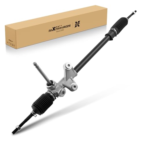
- 【Application】This steering rack fits for Honda Accord 1994 All Engine, Accord 1995-1997 L4 2.2L; for Acura CL 1997 L4 2.2L / 1998-1999 L4 2.3L. For Left Hand Drive Only, comes with Inner Tie Rods; fits the model with Hydraulic Power Steering
- 【OE/Part Number】26-1768, 53010SV4000, 53601SV4A01, 53601SV4A02, 53601SY8A01. Please confirm your original part number or OEM number can match up with one of the part numbers above
- 【Specifications】 Input Shaft Diameter: 0.62 in; Input Shaft Length: 1.57 in; Rack Length: 40.55 in; Thread Length: 2.3 in; Pressure Port Thread Size: M14 x 1.5; Return Port Thread Size: M16 x 1.5; Total Turns Lock To Lock: 3.1, Distance Between Mounting Holes: 3.94 in
- 【Well Made】This rack & pinion is made of high-strength steel + aluminum, with a polished surface and anti-rust, thereby improving the transmission efficiency of driving force and reducing resonance noise
- 【Performance】The steering rack and pinion kit is more responsive and gives compact control ensuring safety when driving through all kinds of bad road conditions
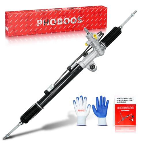
- [Vehicle Fitment] Compatible with Honda Odyssey 2007-2010 V6 3.5L. Refer to Amazon Garage for accurate fitment before purchase.
- [Part Number] Direct replacement for 26-2747, 262747, 53010SHJA02, 53601SHJA06, 53601SHJA84, 53601SHJA86. Compare product images and specifications with your original piece to ensure correct fit.
- [Product Specifications] ①Rack Length (IN): 46.50.②Thread Length (IN): 2.03.③Input Shaft Diameter (IN): 0.75.④Input Shaft Length (IN): 1.99.⑤Pressure port thread size: M14 x 1.5.⑥Return port thread size: M16 x 1.5.⑦Total Turns Lock To Lock: 3.44.
- [Reliable Sealing & Durability] Equipped with high-performance O-rings and oil seals that offer superior resistance to wear, temperature, and leakage. Each unit is tested through 100,000 wear cycles and 1,000,000 fatigue cycles before shipment.
- [Bolt-On Installation & Warranty] Pre-assembled with inner tie rods and dust boots for direct bolt-on fit with OE-matched mounting points. Covered by a 12-month unlimited mileage warranty.
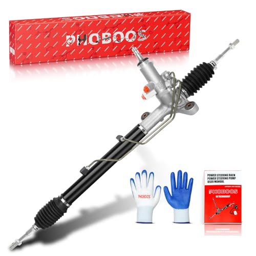
- [Vehicle Fitment] Compatible with Honda Civic 2006-2010 L4 1.8. Refer to Amazon Garage for accurate fitment before purchase. --- For Left Hand Drive Only!!!
- [Part Number] Direct replacement for 26-2718, 262718, 53601SNAA02, 53601SNAA51, 53601SNAA61, 53601SNAA12. Compare product images and specifications with your original piece to ensure correct fit.
- [Product Specifications] ①Rack Length (IN): 40.88.②Thread Length (IN): 1.74.③Input Shaft Diameter (IN): 0.69.④Input Shaft Length (IN): 3.38.⑤Pressure port thread size: M18 x 1.5.⑥Return port thread size: M16 x 1.5.⑦Total Turns Lock To Lock: 2.69.
- [100% Brand-New Product] Built from all-new components on OE production lines. Precisely matched gear and rack pairing ensures original performance and long-term durability—never remanufactured or refurbished.
- [Bolt-On Installation & Warranty] Pre-assembled with inner tie rods and dust boots for direct bolt-on fit with OE-matched mounting points. Covered by a 12-month unlimited mileage warranty.
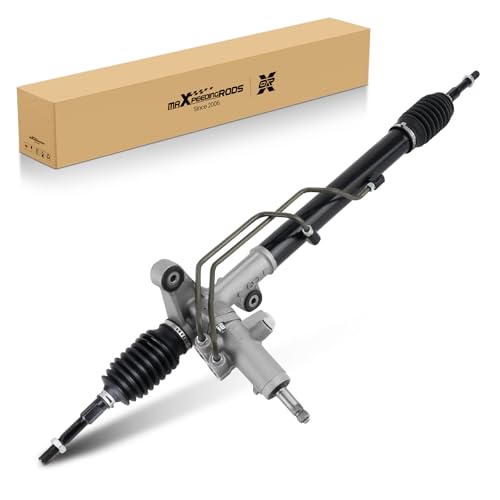
- 【Application】This rack and pinion kit fit for Honda Civic LX, EX, EX-L, DX or GX. 2006-2011 1.8L (Does not fit the Si or Hybrid)
- 【OE/Part Number】26-2718, 80-01395R, 06536SNA506RM, 06536SNE305RM, 18001395-101, 18001395-102, 18001395-103, 244-0089, 26-2763, 53010SNEA01, 53600SNEA04, 53600SNEA04RM, 53601SNAA01, 53601-SNA-A01, 53601SNAA02, 53601-SNA-A02, 53601SNAA12, 53601SNAA51, 53601-SNA-A51, 53601SNAA52, 53601-SNA-A52, 53601SNAA61, 53601SNAA62, 53601-SNA-A62, 97-2718
- 【High Performance】Solves abnormal noise and oil leakage problems, ensures that the steering wheel rotation angle is proportional to the tire rotation angle, and reduces the steering wheel's control force when turning, which makes driving safer
- 【Well Made】With the premium aluminum alloy and iron construction, great anti-rust and anti-corrosive quality for its long service life. We put moderate lubricating oil into this assembly so that it can prevent rust and oxidation
- 【1 Year Warranty】maXpeedingrods offers lifetime technical support and 1-year limited warranty for quality-related issues since the date of purchase. Feel free to contact us if you have any questions
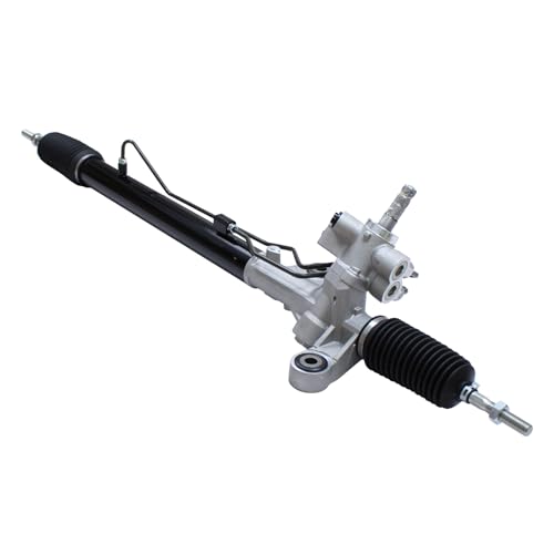
- For Honda Accord 2.4L/3.5L 2008-2012
SEOCONTENT-START
CUSTOMER INFORMATION: The information in this bulletin is intended for use only by skilled technicians who have the proper tools, equipment,
and training to correctly and safely maintain your vehicle. These procedures should not be attempted by “do-it-yourselfers,” and you should not
assume this bulletin applies to your vehicle, or that your vehicle has the condition described. To determine whether this information applies, contact
an authorized Honda automobile dealer.
© 2024 American Honda Motor Co., Inc. – All Rights Reserved Page 1 of 23
Service Bulletin
24-018
March 8, 2024 Version 1
Safety Recall: 2023 Passport, Ridgeline EPS Gearbox Inspection
AFFECTED VEHICLES
Year
Model
Trim Level
VIN Range
2023
Passport
AWD Elite, AWD EX-L, AWD TrailSport
Check the iN VIN status for eligibility.
2023
Ridgeline
AWD RTL, AWD RTL-E, AWD Sport
Check the iN VIN status for eligibility.
BACKGROUND
Due to a manufacturing error, two vehicles may have been produced with an improperly fastened inner ball joint housing and rack end in the steering gearbox assembly. Improperly manufactured electronic power steering (EPS) gearbox assemblies can affect steering function, potentially increasing the risk of a crash or injury.
CUSTOMER NOTIFICATION
Owners of the affected vehicles will be sent a notification of this campaign.
Do an iN VIN status inquiry to make sure the vehicle is shown as eligible.
Some vehicles affected by this campaign may be in your new or used vehicle inventory.
Failure to inspect and repair a vehicle, as necessary, subject to a recall or campaign, may subject your dealership to claims or lawsuits from the customer or anyone else harmed as a result of such failure. To verify if a vehicle in inventory is affected, do a VIN status inquiry before selling it.
CORRECTIVE ACTION
Inspect the serial number, and if there is a match, replace the EPS gearbox assembly.
PARTS INFORMATION
To obtain the correct parts for each vehicle repair, contact your local parts analyst with the vehicle’s VIN and this service bulletin number. The parts center will order the correct parts on behalf of your dealer after the eligibility of the VIN is confirmed.
Part Name
Quantity
Gearbox
1
Flange Bolt (10×35)
2
Flange Bolt (10×16)
2
Flange Bolt (10×103)
1
Flange Bolt (10×30)
3
Flange Bolt (12×80)
3
Split Pin (3.0×22)
2
Page 2 of 23
Steering Joint Yoke Bolt
1
Flange Nut (12mm)
2
Flange Nut (12mm)
2
Flange Nut (12MM)
4
Exhaust Pipe Gasket
2
Self-Lock Nut (10mm)
9
Pre-Chamber Gasket
1
Castle Nut (14mm)
2
Flange Bolt (10×30)
2
Flange Bolt (10×20)
1
Flange Bolt (12×30)
8
Flange Bolt (14×125)
2
Flange Bolt (14×140)
2
Flange Bolt (10×25)
4
Flange Nut (10mm) Ridgeline)
4
O-Ring
1
12 Point Bolt (8×21) (Passport)
4
TOOL INFORMATION
Tool Name
Part Number
Quantity
Steering Wheel Holder Tool
Commercially Available
1
Ball Joint Removal
07MAC-SL00201
1
Ball Joint Removal
071AF-SZNA100
1
Ball Joint Thread Protector
07AAF-SDAA100
1
Subframe Adapter
VSB02C000016
1
Engine Support Hanger
AAR-T1256
1
Engine Hanger Adapter
VSB02C000031
1
Engine Hanger Balance Bar
VSB02C000041
1
Alignment Pin
070AG-SJAA10S
2
Page 3 of 23
WARRANTY CLAIM INFORMATION
NOTE:
• Attach the photo of the EPS label to the warranty claim form. Required photos must be included when submitting your claim, or the claim may be subject to a debit. Retake any unclear photos prior to submitting.
• There are only two EPS serial numbers affected by this activity. Any claims submitted with non-affected serial numbers will be subject to debit.
Operation Number
Description
Flat Rate Time
Defect Code
Symptom Code
Template ID
Failed Part Number
5135A8
Inspect the EPS gearbox label. (Include photos)
0.3 hr
6JB00
LHY00
A24018A
53601-T6Z-A01
5131L9
Replace the EPS gearbox (includes inspection and alignment).
3.7 hr
6JB00
LHY00
A24018B
53601-T6Z-A01
Skill Level: Repair Technician
INSPECTION PROCEDURE
1. Open the hood and wait for the engine to cool down.
2. Using a borescope, locate the label on the EPS gearbox.
Page 4 of 23
3. Inspect the label on the EPS gearbox and check the serial number on the label.
• If the EPS serial number is 012138T0167 or 012138T0126, take a picture of the label, as you will need it to submit your warranty claim. Then go to REPAIR PROCEDURE.
• If the EPS serial number has any other serial number, take a picture of the label and attach it to the warranty claim; no further action is needed.
NOTE: There are only two EPS serial numbers affected by this activity.
REPAIR PROCEDURE
1. Remove the front bulkhead cover.
2. Remove the air intake tube.
Page 5 of 23
3. Disconnect the 12-volt battery.
4. Remove the engine cover.
5. Remove the No. 6 cylinder ignition coil.
6. Remove the engine cowl cover.
Page 6 of 23
7. Install the engine support hanger.
• Install engine hanger adapters (T/N: VSB02C000031)
8. Install the engine hanger balance bar. (T/N: VSB02C000041).
9. Remove the rear engine mount stop.
Page 7 of 23
10. Remove the front engine mount stop.
11. Set the steering column to the center tilt position and to the center telescope position and install the steering wheel holder tool.
12. Remove the driver’s side center console side cover.
Page 8 of 23
13. Disconnect the steering joint from the pinion shaft.
14. Raise the vehicle on a lift.
15. Remove the front wheels 127 N·m (94 lb-ft).
16. Remove the splash shield.
17. Remove the engine undercover.
18. Remove the front subframe stiffener plate.
Page 9 of 23
19. Disconnect the front engine mount actuator.
20. Disconnect the rear engine mount actuator.
21. Disconnect the HO2 Sensor.
22. Remove underfloor TWC (Three Way Catalytic Converter).
23. Loosen both tie rod end nuts from the steering gearbox.
Page 10 of 23
24. Disconnect the tie rod end ball joints.
25. Remove the front ball joint.
26. Disconnect the top stabilizer link bolt.
Page 11 of 23
27. Remove the transmission mount center bolt.
28. Remove the propeller shaft bolts.
Page 12 of 23
29. Remove the transfer case.
30. Install the subframe jack.
31. Remove the front subframe.
Page 13 of 23
32. Remove the engine mount and rear engine mount bracket.
33. Remove the steering gearbox:
• Remove steering gearbox stiffeners.
• Remove the steering gearbox heat shield.
Page 14 of 23
34. Remove the shaft grommet.
35. Remove the tie rod ends.
NOTE: Count the turns it takes to remove the tie rod ends and write it down. This helps make the alignment process easier.
INSTALLATION
NOTE: During the assembly process, replace all required parts.
1. Install the pinion shaft grommet.
• Align the cutout portion with the tab portion.
• The grommet must not have a gap at the mating surface of the grommet and steering gearbox.
2. Install the gearbox heat shield 9.5 N·m (7 lb-ft).
Page 15 of 23
3. Install the tie-rod ends on the steering gearbox.
NOTE: Use the information gathered from step 35 to install the tie rod ends.
4. Install the steering gearbox on the front subframe.
• Tighten the steering gearbox mounting bolt, Install the stiffener mounting bolts, and Install the rear engine mount base bracket mounting bolt to the specified torque in the numbered sequence below.
5. Install the rear engine mount and loosely install the bolts.
Page 16 of 23
6. Raise the subframe and align the front subframe with the subframe alignment pin.
• Tighten the mounting bolts to the specified torque in the numbering sequence shown.
7. Release the subframe jack.
Page 17 of 23
8. Install the transfer case.
• Clean the areas where the transfer assembly contacts the transmission with solvent and dry with compressed air.
• Install a new O-ring.
• Apply grease to the transfer shaft spines. (P/N: 04360-5P8-305).
• Install the transfer assembly with the dowel pin.
• Connect the breather hose by aligning the paint mark to the bracket.
9. Install the propeller shaft bolts.
Page 18 of 23
10. Connect the front and rear engine mount actuators.
11. Connect the stabilizer link.
12. Connect the lower ball joint.
Page 19 of 23
13. Connect the tie rod end ball joint.
• Wipe off grease contamination from the tapered ball joint section and threads.
• Connect the tie rod ball joint to the knuckle.
• Install a new nut and tighten to the specified torque.
• Install a new cotter pin.
14. Install the underfloor TWC.
15. Connect the HO2S sensor.
Page 20 of 23
16. Install the front subframe stiffener plate.
17. Remove the engine support hanger.
Page 21 of 23
18. Install the engine and transmission mounts.
Page 22 of 23
19. Install No. 6 cylinder ignition coil.
20. Install the engine cover.
21. Connect the battery terminal.
22. Install the air intake tube.
23. Install the front bulkhead cover.
24. Install the splash shield.
25. Install the engine undercover.
26. Install the front wheel and torque the nuts to 127 N·m (94 lb-ft).
27. Release the steering wheel.
28. Connect the steering joint.
• Align the bolt hole on the steering joint with the groove around the pinion shaft.
• Loosely install the steering joint bolt.
• Be sure that the joint bolt is securely in the groove in the pinion shaft.
• Pull on the steering joint to make sure that the steering joint is fully seated.
• Tighten the steering joint bolt to the specified torque.
NOTE: Install the steering joint bolt and tighten it within 5 minutes using the specified tightening torque.
Page 23 of 23
• Install the steering joint cover.
NOTE: Check the steering joint cover for damage and cracks. If the steering joint cover is cracked, replace the steering joint cover.
29. Install the center console side cover.
30. Check the steering gearbox for the following symptoms.
• With the tires raised off the ground, check for the following symptoms by turning the steering wheel fully to the right and left several times.
• If everything is OK, continue to the next step.
Symptom
Probable Cause
Rubbing sound coming from the lower steering area.
The steering column joint is contacting the cover.
Grating sound from the lower steering column area or a rough feeling during steering.
Poor engagement of the pinion splines.
Noise from around the steering wheel during steering.
Poor engagement of the SRS cable reel with the steering wheel or a damaged cable reel.
31. Check these items with the vehicle on the ground:
• Start the engine, allow it to idle, and turn the steering wheel from lock to lock several times.
• Check that the EPS indicator does not come on.
• Check the steering wheel spoke angle. If steering spoke angles to the right and left are not equal (steering wheel and rack are not centered), reposition the steering wheel on the steering column shaft spines.
32. Do a four-wheel alignment.
33. Do a VSA sensor Neutral position memorization.
34. Do a steering angle sensor neutral position learning procedure.
**************************************************************************************************************
Next Unread Message View Message
DATE: March 8, 2024
TO: All Honda Sales, Service & Parts Managers, and Personnel
FROM: Brad Ortloff, Manager of Auto Campaigns and Recalls
Re: Stop Sale/Safety Recall: 2023 Passport, Ridgeline EPS Gearbox Assembly Inspection
On March 7, 2024, American Honda notified NHTSA of a stop sale and safety recall for 245 units of model year 2023 Passport and Ridgeline which may have improperly
manufactured electronic power steering (EPS) gearbox assemblies that can affect steering function, potentially increasing the risk of a crash or injury. Refer to your
eResponsibility report or perform an iN VIN status inquiry to determine which units in your inventory are affected.
Failure to inspect and repair a vehicle as necessary prior to sale or before returning the vehicle to a customer may subject your dealership to claims or lawsuits.
BACKGROUND
Due to a manufacturing error, two vehicles may have been produced with an improperly fastened inner ball joint housing and rack end in the steering gearbox assembly.
REPAIR
Inspect the EPS gearbox serial number and if there is a match, replace the EPS gearbox assembly.
PARTS
Parts will only be available by contacting your local Parts Analyst upon confirmation of an affected unit.
TOOLS
There are no special tools required for this recall.
SERVICE BULLETIN
Service Bulletin 24-018, Safety Recall: 2023 Passport, Ridgeline EPS Gearbox Inspection has posted to the Service Information System (SIS) as of March 8, 2024. It
includes inspection, repair, parts, and warranty claim information related to this recall.
CUSTOMER NOTIFICATION
American Honda expects to begin customer notification in mid-April 2024.
As always, perform an iN VIN status inquiry for all vehicles passing through your dealership to determine eligibility for any open campaigns.
Sent on 03 08 2024 Expires on 05 26 2024
From Brad Ortloff, Manager of Auto Campaigns and Recalls
Subject Stop Sale/Safety Recall: 2023 Passport, Ridgeline EPS Gearbox Assembly Inspectio
INTERACTIVE NETWORK
American Honda Motor Co., Inc. Page 1 of 1
**************************************************************************************************************
OMB Control No.: 2127-0004
Part 573 Safety Recall Report 24V-184
The information contained in this report was submitted pursuant to 49 CFR §573
Manufacturer Name : Submission Date :
Honda (American Honda Motor Co.) MAR 07, 2024 NHTSA Recall No. : 24V-184 Manufacturer Recall No. : LHY Manufacturer Information :
Manufacturer Name : Honda (American Honda Motor Co.) Address : 1919 Torrance Blvd.
Torrance CA 90501
Company phone : 1-888-234-2138 Population :
Number of potentially involved : 245 Estimated percentage with defect : 1 % Vehicle Information : Vehicle 1 : 2023-2023 Honda Passport Vehicle Type : LIGHT VEHICLES Body Style : SUV Power Train : GAS
Descriptive Information : The recall population was determined based on manufacturing records. The production range reflects all possible vehicles that could experience the problem.
Production Dates : SEP 21, 2023 – SEP 22, 2023
VIN Range 1 : Begin : NR End : NR Not sequential Vehicle 2 : 2023-2023 Honda Ridgeline Vehicle Type : LIGHT VEHICLES Body Style : PICKUP TRUCK Power Train : GAS
Descriptive Information : The recall population was determined based on manufacturing records. The production range reflects all possible vehicles that could experience the problem.
Production Dates : SEP 21, 2023 – SEP 22, 2023
VIN Range 1 : Begin : NR End : NR Not sequential Description of Defect :
Description of the Defect : The inner ball joint housing may not have been fastened to the correct torque specification, resulting in a loose inner ball joint housing that can detach from the steering rack.
FMVSS 1 : NR FMVSS 2 : NR
Description of the Safety Risk : If the inner ball joint housing detaches from the steering rack, the ability to
steer the vehicle as intended can be affected, increasing the risk of a crash or Part 573 Safety Recall Report 24V-184 Page 2 injury.
Description of the Cause : Due to a lack of maintenance to the steering gearbox workbench (pallet & clamps), the steering gearbox was improperly secured to the workbench, triggering an alarm during the tightening procedure. To subvert the alarm, the operator inappropriately performed the procedure by applying the torque wrench to the torque analyzer rather than the part itself. Identification of Any Warning
that can Occur : Abnormal noise and/or vibration from the steering system. Involved Components : Component Name 1 : Gearbox Assembly: Steering (Rack and Pinion) Component Description : Gearbox Assembly: Steering (Rack and Pinion) Component Part Number : 53400-T6Z-A010-M1 Supplier Identification : Component Manufacturer
Name : NSK Steering Systems Americas-Dyersburg Address : 2962 Fort Hudson Rd
Dyersburg Tennessee 38024
Country : United States Chronology :
September 22, 2023
Three vehicles with steering issues were found at the Honda Alabama Auto Plant. Honda began to investigate the issue. February 6, 2024
Honda investigated and analyzed the suspected population of vehicles. March 1, 2024
Honda determined that a defect related to motor vehicle safety existed and decided to conduct a safety recall. As of March 1, 2024, Honda has not received any warranty claims, reports of injuries or deaths related to this issue. The information contained in this report was submitted pursuant to 49 CFR §573 Part 573 Safety Recall Report 24V-184
Page 3
The information contained in this report was submitted pursuant to 49 CFR §573
Description of Remedy :
Description of Remedy Program : Registered owners of all affected vehicles will be contacted by mail and
asked to take their vehicle to an authorized Honda dealer. The dealer will inspect and, if necessary, replace the steering gearbox with a non-defective part.
Owners who have paid to have these repairs completed at their own expense may be eligible for reimbursement, in accord with the recall reimbursement plan on file with NHTSA.
How Remedy Component Differs from Recalled Component :
Identify How/When Recall Condition was Corrected in Production :
The remedy components are properly assembled with the correct fastening procedures.
The supplier inspected and repaired the steering gearbox workbenches (pallet and clamps) on September 24, 2023, initiated pre-shift workbench inspections, and improved operator training. Recall Schedule :
Description of Recall Schedule : Dealer notification is scheduled to begin and end on or about 3/8/2024.
Owner notification is scheduled to begin and end on or about 4/15/2024.
Planned Dealer Notification Date : MAR 08, 2024 – MAR 08, 2024
Planned Owner Notification Date : APR 15, 2024 – APR 15, 2024
* NR – Not Reported
**************************************************************************************************************
**************************************************************************************************************
**************************************************************************************************************
SEOCONTENT-END
This product presentation was made with AAWP plugin.