
A21-093
December 3, 2021
Version 1
Safety Recall: 2022 CR-V Hybrid Left Side Driveshaft
AFFECTED VEHICLES
| Year | Model | Trim | VIN Range |
| 2022 | CR-V Hybrid | All | Check the iN VIN status for eligibility. |
BACKGROUND
A small number of 2022 CR-V Hybrids were manufactured with front driveshafts that have constant velocity joints (CV Joint) which were improperly manufactured. If the complete driveshaft is not replaced it could result in premature wear, excessive noise, vibration, and over time possible part failure. The affected vehicles will only have a left side front driveshaft that will need to be replaced. No vehicles will require both front driveshafts to be replaced. The VIN inquiry system will identify which vehicle needs the left side front driveshaft to be replaced.
CUSTOMER NOTIFICATION
Owners of affected vehicles will be sent a notification of this campaign.
Do an iN VIN status inquiry to make sure the vehicle is shown as eligible.
Some vehicles affected by this campaign may be in your new or used vehicle inventory.
Failure to repair a vehicle subject to a recall or campaign may subject your dealership to claims or lawsuits from the customer or anyone else harmed as a result of such failure. To see if a vehicle in inventory is affected by this safety recall, do a VIN status inquiry before selling it.
CORRECTIVE ACTION
Replace left front driveshaft with new part listed in the parts information
PARTS INFORMATION
| Part Name | Part Number | Quantity |
| Left Driveshaft Assembly | 44306-TMA-H01 | 1 |
| Spindle Nut | 90305-S3V-A11 | 1 |
| Self Lock Nut | 90215-SB0-003 | 3 |
| Drain Plug Washer (18 mm) | 90471-PX4-000 | 1 |
| Drain Plug Washer (20 mm) | 94109-20000 | 1 |
REQUIRED MATERIALS
| Part Name | Part Number | Quantity |
| ATF-DW1 | 08200-9008 | 3 |
| M77 (One tube will repair 12 vehicles) | 08798-9010 | 1 |
REPAIR PROCEDURE
1. Lift vehicle and remove left front wheel.
2. Pry up the stake on the spindle nut and remove the spindle nut.
3. Remove the engine undercover.
4. Remove the transmission drain plug and sealing washer. Allow the transmission fluid to drain.
NOTE: Be careful the ATF may be hot.
5. Install the transmission drain plug with a new washer.
6. Disconnect the lower arm ball joint.
7. Disconnect the outboard joint.
8. Using a pry bar, pry the inboard joint from the differential and remove the driveshaft assembly.
NOTE:
- Be careful not to damage the oil seal when prying on the inboard joint.
- Do not pull on the driveshaft, or the inboard joint may come apart.
- When removing the inboard joint from the differential make sure it is straight to avoid damaging the oil seal.
9. Confirm the set ring is in the grove on the new driveshaft. Then, insert the inboard end of the driveshaft into the differential, until the set ring locks in the groove.
10. Make sure the bearing and spindle are clean of any debris or rust particles using a shop towel and/or compressed air. Then apply about 3 g (0.11 oz) of M-77 Assembly Paste (P/N 08798-9010) to the contact area of the outboard joint and the front wheel bearings.
11. Apply lube to the spindle area of the outboard shaft and insert the shaft thru the knuckle.
NOTE: Do not apply any to the threads of the spindle or nut.
12. Install the lower ball joint and torque to the specified value and the order shown.
13. Install the new spindle nut and torque it to328 N.m (242 lb-ft) using a torque wrench. If you are going to use an Air or Battery Powered Impact Gun to install the nut, make sure to turn down the air or power so you do not overtighten it, then torque it to specification using a torque wrench.
NOTE: Do not use a stake, punch, or screwdriver in the brake rotor to keep it from moving, have an assistant press on the brakes while you are tightening.
14. Use a drift to stake the spindle nut shoulder against the driveshaft.
NOTE:
- Check the spindle nut shoulder as shown.
- Be careful not to crack the spindle nut when staking it.
15. Install the front wheel.
16. Turn the wheel by hand and make sure there is no interference between the driveshaft and surrounding parts.
17. Remove the filler plug and fill the transmission to the proper level as shown.
NOTE: Using the wrong type of fluid will damage the transmission (e-CVT).
18. Enter the maintenance mode, then start the engine.
19. Warm up the engine by raising the engine speed to around 3,000 rpm until the cooling fan(s) comes on.
20. Turn the engine off.
21. Remove the filler plug with the sealing washer.
NOTE: Be careful not to burn yourself by the hot part.
22. Make sure the ATF level is at the proper level.
- If the ATF is overfilled, drain the ATF from the filler plug hole to the proper level.
- If the ATF is low, inspect and repair any external leaks. If there are no leaks, fill the transmission (e-CVT) with the recommended fluid through the filler plug hole to the proper level. Always use genuine Honda ATF DW-1.
23. Install the engine undercover.
24. Check the wheel alignment.
25. Test-drive the vehicle.
END
21V939 – Driveshaft May Fail – 2021 Acura RDX & 2022 Honda CR-V Hybrid
Safety Recall: 2022 Honda CR-V Hybrid Left Side Driveshaft
Remedy Instructions and TSB
RCRIT-21V939-9831.pdf 578.063KB
Latest Recalls Documents

- 100% Brand New item,High Quality Tools,Has a nice Black oxide finish.
- Nut size:2 1/4",Fits 1/2 Rachet/Breaker bar.
- Compatible With: 2007 - Present/now For Harley Twin Cams/2006 -Present/now For Harley for Dyna
- The tool has a Threaded Bushing and can be used with a 1/2" drive ratchet or breaker bar.
- This tool is a Main Shaft Sprocket Wrench Tool for the 2 1/4" Nutl ,comes with a threaded bushing.his kit fits for all Harley Davidson front transmission pulley 2-1/4"
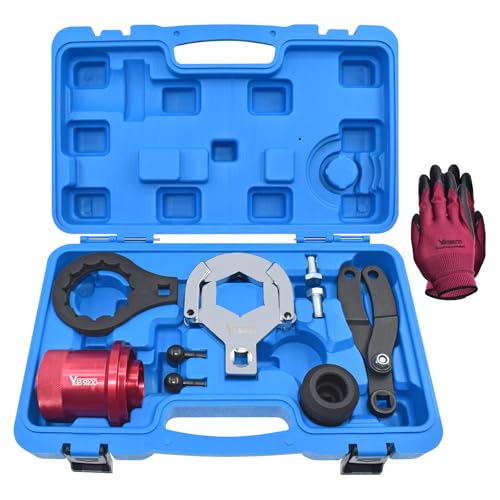
- Yuesstloo rear axle installer remover kit is used to install and remove the screw nut between the rear drive shaft and the differential. Also can be used to replace the differential shaft seal.
- Compatible with BMW E70 E90 E91 E92 X3 X5 X6 RWD 4WD. OEM Equivalent Part Number: 335040, 335050, 335060, 335080, 230020.
- Made of high quality steel, with high hardness, not easy to break and deform.
- Convenient to transport and store. Comes with a carrying case, all parts are neatly placed. And we prepare a pair of gloves for you to use when using the tool.
- If there is some problem with our products, you can get help from us. Customer satisfaction is our top priority.
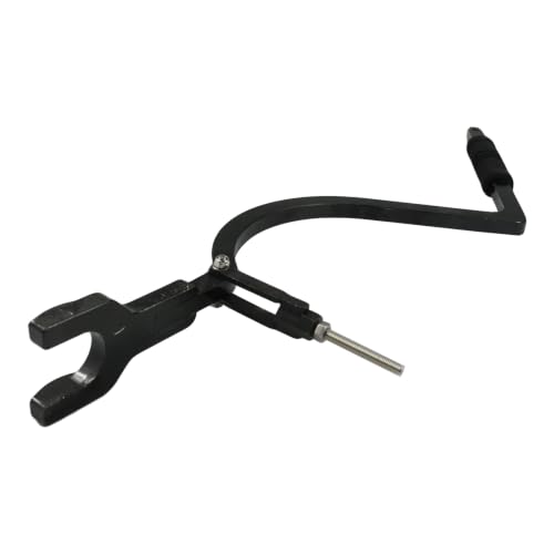
- 【Part Numbers】Compatible With 529036026 Drive Shaft Carbon Seal Tool. Designed To Help Remove The Drive Shaft C-Clip, Floating Ring And Carbon Seal Retaining Ring On Compatible Sea-Doo Models
- 【Application】Drive Shaft C-Clip Remover Tool Compatible With Sea-Doo GTI, GTR, GTS, GTX, RXP, RXT, Wake And Fish Pro Models With 1503 Engines, Including GTI 130, GTI SE 130, GTI SE 155, GTR 215, GTS 130, GTX 155, GTX 215 And Related Models. Compatible With Sea-Doo RXP 155, RXP 215, RXP-X 255, RXP-X 260, RXT 215, RXT 260, RXT-X 255, RXT-X 260, Wake 155, Wake 215, Fish Pro 155 And Related 4-TEC Models. Please Check The Full Fitment Before Purchase
- 【Specification】Made Of 40Cr Steel With CNC Machined Construction For Accurate Fit And Stable Use. The Adjustable Threaded Rod Helps Fit Different Engine Compartments And Provides Leverage To Push Back The Metal Hat For C-Clip Removal
- 【Package Includes】1 × Drive Shaft C-Clip Remover Tool. Designed To Make Carbon Seal, Floating Ring And Drive Shaft Service More Convenient On Compatible Models
- 【Notice】This Is A Replacement Tool, Not An Original Tool. Please Carefully Check Your Original Tool Number, Vehicle Model, Year, Engine Type, Working Space And Product Pictures Before Purchase To Make Sure This Tool Fits Your Repair Needs
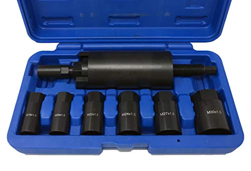
- This Drive Shaft Puller kit is designed for pulling drive shafts into hubs
- Kit comes with six different size adapters: M16 x 1. 5 (Subaru), M20 x 1. 5 (VW/Audi/Porsche), M22 x 1. 5 (BMW E30), M24 x 1. 5 (BMW E36 & Mercedes Benz W203), M27 x 1. 5 (BMW E32/E34/E38/E39/E53) and M30 x 1. 5 (BMW E32/E36/E34)
- Applications: BMW, VW, Audi, Porsche, Mercedes Benz & Subaru
- Visit ctatools for application details
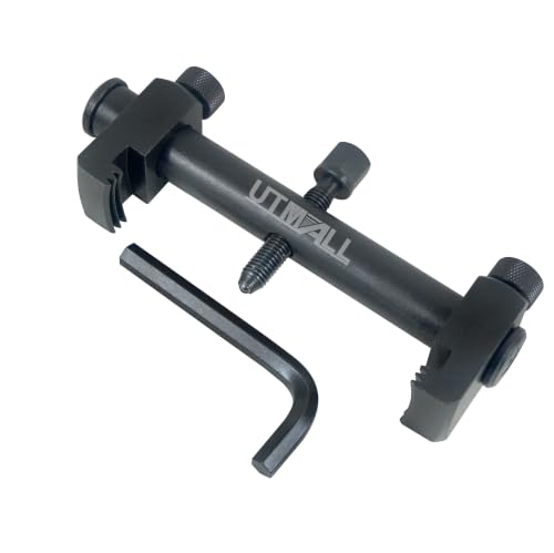
- Designed for removal of stubborn or seized ribbed crankshaft and auxiliary pulleys.
- Suitable for use on crankshafts, alternators, air conditions unit, and Water pumps
- Allows removal without the risk of damaging the pulley in restricted engine bays.Low profile arms allow use in restricted engine bays.
- Max opening jaws 6.3" (165mm), Close: 1-1/4" (35mm)
- We provide 12-month warranty service. If the tools have quality problems, please contact us and apply for replacement and return to ensure the shopping experience.
SEOCONTENT-START
Service Bulletin 21-093 December 3, 2021 Version 1 Safety Recall: 2022 CR-V Hybrid Left Side Driveshaft AFFECTED VEHICLES Year Model Trim VIN Range 2022 CR-V Hybrid All Check the iN VIN status for eligibility. BACKGROUND A small number of 2022 CR-V Hybrids were manufactured with front driveshafts that have constant velocity joints (CV Joint) which were improperly manufactured. If the complete driveshaft is not replaced it could result in premature wear, excessive noise, vibration, and over time possible part failure. The affected vehicles will only have a left side front driveshaft that will need to be replaced. No vehicles will require both front driveshafts to be replaced. The VIN inquiry system will identify which vehicle needs the left side front driveshaft to be replaced. CUSTOMER NOTIFICATION Owners of affected vehicles will be sent a notification of this campaign. Do an iN VIN status inquiry to make sure the vehicle is shown as eligible. Some vehicles affected by this campaign may be in your new or used vehicle inventory. Failure to repair a vehicle subject to a recall or campaign may subject your dealership to claims or lawsuits from the customer or anyone else harmed as a result of such failure. To see if a vehicle in inventory is affected by this safety recall, do a VIN status inquiry before selling it. CORRECTIVE ACTION Replace left front driveshaft with new part listed in the parts information PARTS INFORMATION Part Name Part Number Quantity Left Driveshaft Assembly 44306-TMA-H01 1 Spindle Nut 90305-S3V-A11 1 Self Lock Nut 90215-SB0-003 3 Drain Plug Washer (18 mm) 90471-PX4-000 1 Drain Plug Washer (20 mm) 94109-20000 1 CUSTOMER INFORMATION:The information in this bulletin is intended for use only by skilled technicians who have the proper tools, equipment, and training to correctly and safely maintain your vehicle. These procedures should not be attempted by “do-it-yourselfers,” and you should not assume this bulletin applies to your vehicle, or that your vehicle has the condition described. To determine whether this information applies, contact an authorized Honda automobile dealer. © 2021 American Honda Motor Co., Inc. — All Rights Reserved Page 1 of 9 REQUIRED MATERIALS Part Name Part Number Quantity ATF-DW1 08200-9008 3 M77 (One tube will repair 12 vehicles) 08798-9010 1 WARRANTY CLAIM INFORMATION Operation Number Description Flat Rate Time Defect Code Symptom Code Template ID Failed Part Number 2191CJ Replace left front driveshaft assembly only. (Includes time for alignment) 1.1 hr 6DF00 NBW00 A21093A 44306-TMA-H01 REPAIR PROCEDURE 1. Lift vehicle and remove left front wheel. Page 2 of 9 2. Pry up the stake on the spindle nut and remove the spindle nut. 3. Remove the engine undercover. Page 3 of 9 4. Remove the transmission drain plug and sealing washer. Allow the transmission fluid to drain. NOTE: Be careful the ATF may be hot. 5. Install the transmission drain plug with a new washer. 6. Disconnect the lower arm ball joint. 7. Disconnect the outboard joint. Page 4 of 9 8. Using a pry bar, pry the inboard joint from the differential and remove the driveshaft assembly. NOTE: • Be careful not to damage the oil seal when prying on the inboard joint. • Do not pull on the driveshaft, or the inboard joint may come apart. • When removing the inboard joint from the differential make sure it is straight to avoid damaging the oil seal. 9. Confirm the set ring is in the grove on the new driveshaft. Then, insert the inboard end of the driveshaft into the differential, until the set ring locks in the groove. Page 5 of 9 10. Make sure the bearing and spindle are clean of any debris or rust particles using a shop towel and/or compressed air. Then apply about 3 g (0.11 oz) of M-77 Assembly Paste (P/N 08798-9010) to the contact area of the outboard joint and the front wheel bearings. 11. Apply lube to the spindle area of the outboard shaft and insert the shaft thru the knuckle. NOTE: Do not apply any to the threads of the spindle or nut. 12. Install the lower ball joint and torque to the specified value and the order shown. Page 6 of 9 13. Install the new spindle nut and torque it to328 N.m (242 lb-ft) using a torque wrench. If you are going to use an Air or Battery Powered Impact Gun to install the nut, make sure to turn down the air or power so you do not overtighten it, then torque it to specification using a torque wrench. NOTE: Do not use a stake, punch, or screwdriver in the brake rotor to keep it from moving, have an assistant press on the brakes while you are tightening. 14. Use a drift to stake the spindle nut shoulder against the driveshaft. NOTE: • Check the spindle nut shoulder as shown. • Be careful not to crack the spindle nut when staking it. Page 7 of 9 15. Install the front wheel. 16. Turn the wheel by hand and make sure there is no interference between the driveshaft and surrounding parts. 17. Remove the filler plug and fill the transmission to the proper level as shown. NOTE: Using the wrong type of fluid will damage the transmission (e-CVT). 18. Enter the maintenance mode, then start the engine. 19. Warm up the engine by raising the engine speed to around 3,000 rpm until the cooling fan(s) comes on. 20. Turn the engine off. 21. Remove the filler plug with the sealing washer. NOTE: Be careful not to burn yourself by the hot part. Page 8 of 9 22. Make sure the ATF level is at the proper level. • If the ATF is overfilled, drain the ATF from the filler plug hole to the proper level. • If the ATF is low, inspect and repair any external leaks. If there are no leaks, fill the transmission (e-CVT) with the recommended fluid through the filler plug hole to the proper level. Always use genuine Honda ATF DW-1. 23. Install the engine undercover. 24. Check the wheel alignment. 25. Test-drive the vehicle. END Page 9 of 9
**************************************************************************************************************
SEOCONTENT-END
This product presentation was made with AAWP plugin.