
January 9, 2018
Passenger Frontal Air Bag Inflator May Explode
An inflator explosion may result in sharp metal fragments striking the driver or other occupants resulting in serious injury or death.
NHTSA Campaign Number: 18V042
Manufacturer Honda (American Honda Motor Co.)
Components AIR BAGS
Potential Number of Units Affected 691,726
Summary
Honda (American Honda Motor Co.) is recalling certain 2010-2013 Acura TSX, ZDX, Honda Accord Crosstour, Fit, Insight and Pilot vehicles, 2011-13 Acura TSX Sportswagon, 2010-2012 Honda Accord,, 2010-2011 Honda Civic, Civic NGV, Civic Hybrid and CR-V vehicles and 2013 Honda FCX Clarity and Fit EV vehicles ever registered in the states of Alabama, California, Florida, Georgia, Hawaii, Louisiana, Mississippi, South Carolina, Texas, Puerto Rico, American Samoa, Guam, the Northern Mariana Islands (Saipan), and the U.S. Virgin Islands or “Zone A.”
Additionally, Honda is recalling certain 2010-2012 Acura TSX, Honda Accord, Accord Crosstour, Fit and Pilot, 2010-2011 Honda Civic, Civic NGV, Civic Hybrid and CR-V, and 2010 Acura ZDX and Honda Insight vehicles ever registered in the states of Arizona, Arkansas, Delaware, District of Columbia, Illinois, Indiana, Kansas, Kentucky, Maryland, Missouri, Nebraska, Nevada, New Jersey, New Mexico, North Carolina, Ohio, Oklahoma, Pennsylvania, Tennessee, Virginia, and West Virginia or “Zone B.”
Unless included in Zones A or B above, Honda is recalling certain 2009 Acura TSX, Honda Accord, Civic, Civic NGV, Civic Hybrid, CR-V, Fit, and Pilot vehicles ever registered in the states of Alaska, Colorado, Connecticut, Idaho, Iowa, Maine, Massachusetts, Michigan, Minnesota, Montana, New Hampshire, New York, North Dakota, Oregon, Rhode Island, South Dakota, Utah, Vermont, Washington, Wisconsin, and Wyoming or “Zone C.”
These vehicles are equipped with certain air bag inflators assembled as part of the frontal air bag modules, and used as original equipment or replacement equipment (such as after a vehicle crash necessitating replacement of the original air bags), may explode due to propellant degradation occurring after long-term exposure to higher absolute humidity, temperature and temperature cycling.
Remedy
Honda will notify owners, and dealers will replace the passenger frontal air bag inflator, free of charge. The recall began February 16, 2018. Owners may contact Honda customer service at 1-888-234-2138. Honda’s numbers for this recall are B0K and L0J.
Notes
Owners may also contact the National Highway Traffic Safety Administration Vehicle Safety Hotline at 1-888-327-4236 (TTY 1-800-424-9153), or go to www.safercar.gov.
Check if your Honda has a Recall
Service Bulletin
A18-002
January 10, 2018
Version 1
Safety Recall: Takata Front Passenger’s Airbag Inflator (Phase 3)
Following NHTSA direction, there are five phases based on three different zones.
If the iN VIN status inquiry directs you to do this campaign, follow the applicable procedure regardless of where the vehicle is currently located because it may have moved between different states. Make sure you file a claim using the correct warranty claim information to avoid your claim being rejected.
AFFECTED VEHICLES
Zone A
| Year | Model | Trim | VIN Range |
| 2009–12 | Accord | ALL | Check the iN VIN status for eligibility |
| 2010–13 | Crosstour | ALL V6 | Check the iN VIN status for eligibility |
| 2012-13 | Crosstour | ALL L4 | Check the iN VIN status for eligibility |
| 2009–11 | Civic | ALL | Check the iN VIN status for eligibility |
| 2009–11 | Civic CNG | ALL | Check the iN VIN status for eligibility |
| 2009–11 | Civic Hybrid | ALL | Check the iN VIN status for eligibility |
| 2009–11 | CR-V | ALL | Check the iN VIN status for eligibility |
| 2009–13 | Fit | ALL | Check the iN VIN status for eligibility |
| 2013 | Fit EV | ALL | Check the iN VIN status for eligibility |
| 2010–13 | Insight | ALL | Check the iN VIN status for eligibility |
| 2009–13 | Pilot | ALL | Check the iN VIN status for eligibility |
Zone A applies to model year 2009 through 2013 vehicles that are located or ever registered in: Alabama, California, Florida, Georgia, Hawaii, Louisiana, Mississippi, South Carolina, Texas, Puerto Rico, American Samoa, Guam, the Northern Mariana Islands (Saipan), and the U.S. Virgin Islands.
Zone B
| Year | Model | Trim | VIN Range |
| 2009–10 | Accord | ALL | Check the iN VIN status for eligibility |
| 2010 | Crosstour | ALL V6 | Check the iN VIN status for eligibility |
| 2009–10 | Civic | ALL | Check the iN VIN status for eligibility |
| 2009–10 | Civic CNG | ALL | Check the iN VIN status for eligibility |
| 2009–10 | Civic Hybrid | ALL | Check the iN VIN status for eligibility |
| 2009–10 | CR-V | ALL | Check the iN VIN status for eligibility |
| 2009–10 | Fit | ALL | Check the iN VIN status for eligibility |
| 2009–10 | Pilot | ALL | Check the iN VIN status for eligibility |
Zone B applies to model year 2009 through 2010 vehicles that are located or ever registered in: Arizona, Arkansas, Delaware, District of Columbia, Illinois, Indiana, Kansas, Kentucky, Maryland, Missouri, Nebraska, Nevada, New Jersey, New Mexico, North Carolina, Ohio, Oklahoma, Pennsylvania, Tennessee, Virginia, and West Virginia.
Zone C
| Year | Model | Trim | VIN Range |
| 2009 | Accord | ALL | Check the iN VIN status for eligibility |
| 2009 | Civic | ALL | Check the iN VIN status for eligibility |
| 2009 | Civic CNG | ALL | Check the iN VIN status for eligibility |
| 2009 | Civic Hybrid | ALL | Check the iN VIN status for eligibility |
| 2009 | CR-V | ALL | Check the iN VIN status for eligibility |
Zone C applies to model year 2009 vehicles that are located in: Alaska, Colorado, Connecticut, Idaho, Iowa, Maine, Massachusetts, Michigan, Minnesota, Montana, New Hampshire, New York, North Dakota, Oregon, Rhode Island, South Dakota, Utah, Vermont, Washington, Wisconsin, and Wyoming.
REPAIR PROCEDURE TABLE OF CONTENTS
This bulletin has repair procedures for several vehicles. Make sure to use the applicable procedure for the vehicle you are working on.
| Vehicle | Page |
| Accord and Crosstour | 6 |
| Civic, Civic CNG, and Civic Hybrid | 17 |
| CR-V | 27 |
| Fit and Fit EV | 36 |
| Insight | 47 |
| Pilot | 58 |
BACKGROUND
NHTSA and its independent expert reviewed the findings of three independent investigations into the Takata air bag inflator ruptures. According to NHTSA, the combination of time, high temperature fluctuations, and humidity contribute to the degradation of the propellant in the inflators. NHTSA has concluded that this degradation can cause the propellant to burn too quickly, creating more pressure than the inflator can withstand and, in extreme cases, causing the inflator to rupture and send shrapnel through the airbag toward vehicle occupants. NHTSA is prioritizing the recall of airbag inflators based on the risk of injury or death to vehicle occupants.
Currently there are five planned phases to this campaign. The subsequent phases will launch at a future date per NHTSA direction, but it will be several years before the final phase launches. Additionally, AHM may add new affected models or affected years to each phase. Always do an iN VIN status inquiry to see if a vehicle is affected.
For more information about these inflator recalls, go to www.safercar.gov and use keyword TAKATA.
NOTE
If the VIN status inquiry indicates that the vehicle is subject to any open safety recalls, including the driver’s airbag inflator, make sure to also complete those recall repairs before returning the vehicle to the customer. If you are unable to complete any open recall, advise the customer of the recall status and when the recall could be completed.
Make sure you review this service bulletin for installation instructions and details about model applicability.
CUSTOMER NOTIFICATION
Owners of affected vehicles will be sent a notification of this campaign. Do an iN VIN status inquiry to make sure the vehicle is shown as eligible.
Some vehicles affected by this campaign may be in your used vehicle inventory.
Failure to repair a vehicle subject to a recall or campaign may subject your dealership to claims or lawsuits from the customer or anyone else harmed as a result of such failure. To see if a vehicle in inventory is affected by this safety recall, do a VIN status inquiry before selling it.
CORRECTIVE ACTION
Replace the passenger’s airbag inflator, then return the original, undeployed inflator as directed.
PARTS INFORMATION
| Part Name | Part Number | Quantity |
| 2009–12 Accord Front Passenger’s Airbag Inflator Kit | 04790-TA0-407 | 1 |
| 2010–13 Accord Crosstour (V6 & L4) Front Passenger’s Airbag Inflator Kit | 04790-TA0-407 | 1 |
| 2009–11 Civic Front Passenger’s Airbag Inflator Kit (Applies Civic, Civic CNG and Civic Hybrid) | 04790-SNA-407 | 1 |
| 2009–11 CR-V Front Passenger’s Airbag Inflator Kit | 04790-SWA-407 | 1 |
| 2009–13 Fit & 2013 Fit EV Front Passenger’s Airbag Inflator Kit | 04790-TK6-407 | 1 |
| 2010–13 Insight Front Passenger’s Airbag Inflator Kit | 04790-TM8-407 | 1 |
| 2009–13 Pilot Front Passenger’s Airbag Inflator Kit | 04790-SZA-407 | 1 |
NOTES
- The inflator kit box must be used to return the recalled inflator to its Be careful not to damage the inflator kit box.
- If the recalled, undeployed inflator is not returned, the warranty claim for that vehicle will be charged back to your dealership.
- To return the undeployed inflators, follow the shipping instructions outlined in PIB A15-0002, Inflator Kit Return Process.
- Parts staff can scan the part number and serial number from the outside of the box into the warranty claim by using the Controlled Part Serial No. screen and scanning the applicable information. Refer to the Job Aid Ordering and Managing Replacement Inflators for more information.
REQUIRED TOOLS
| Tool Name | Part Number | Quantity |
| PSPI6 Gauge Tool | 070AJ-TA00A00
07AAJ-TA0AA00 | 1 |
NOTES
- Each dealer was sent over 10 tools. If you need more, the gauge is available for dealer ordering.
- This tool for use on the inflators with blue collars only.
WARRANTY CLAIM INFORMATION
NOTES
- Process claims as quickly as possible so that resources can be properly allocated.
- Enter the part number of the inflator that you received into the warranty claim, not the part number that you For more information, refer to step 6 of REPAIR PROCEDURE.
- To avoid non-payment of warranty claims, the serial number on the box of the new airbag inflator must be entered into the warranty claim. For more information, refer to step 6 of REPAIR PROCEDURE.
- To avoid a warranty claim being charged back to your dealership, you must return the recalled, undeployed inflator to its supplier. Follow the shipping instructions outlined in PIB A15-0002, Inflator Kit Return Process.
- The serial number is encoded into the bar code printed on the label inside of the box and on a label attached to the outside of the box. If your dealership uses a scanner, you can scan the serial number from either place into the claim.
- The part number is encoded into a barcode attached to the outside of the If your dealership uses a scanner, you can scan the part number into the claim.
- If you confuse the serial number and part number when entering the claim information, your claim will automatically be rejected.
- For more information about scanning and filing airbag inflator recall claims, refer to Ordering and Managing Replacement Inflators. From the iN, select Service, Warranty, then Claims Reference Guide. Under HOT TIPS/ TOPICS, select Ordering and Managing Replacement Inflators.
- Each VIN is assigned to a specific campaign. Make sure you file a claim using the correct warranty claim information to avoid your claim being rejected.
Replacing the front passenger’s airbag inflator
| Year/ Model | Operation Number | Replacement Part Number | Flat Rate Time | Defect Code | Symptom Code | Template ID | Failed Part Number |
| 2009–12 Accord | 7541D1 | 04790-TA0-407 | 0.7 hr | 6EC00 | B0K00 | A18002A | 77820-TA0-A80ZC |
| 2012-13 Crosstour (L4)
2010-13 Crosstour (V6) | 7541D1 | 04790-TA0-407 | 0.7 hr | 6EC00 | B0K00 | A18002C | 77820-TA0-A80ZC |
| 2009–11 Civic (Includes CNG & Hybrid) | 7541D1 | 04790-SNA-407 | 0.8 hr | 6EC00 | B0K00 | A18002E | 77820-SNA-A82ZA |
| 2009–11 CR-V | 7541D1 | 04790-SWA-407 | 0.7 hr | 6EC00 | B0K00 | A18002G | 77820-SWA-A80ZA |
| 2009–13 Fit & 2013 FIT EV | 7541D1 | 04790-TK6-407 | 0.9 hr | 6EC00 | B0K00 | A18002I | 77820-TK6-A80ZA |
| 2010–13 Insight | 7541D1 | 04790-TM8-407 | 0.6 hr | 6EC00 | B0K00 | A18002K | 77820-TM8-A80ZB |
| 2009–13 Pilot | 7541D1 | 04790-SZA-407 | 0.6 hr | 6EC00 | B0K00 | A18002M | 77851-SZA-A12 |
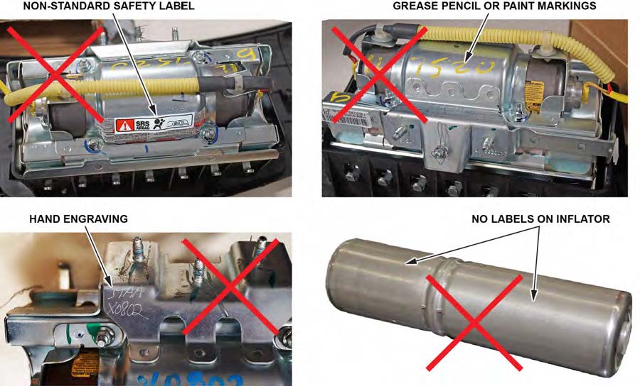
IDENTIFYING COUNTERFEIT AIRBAGS
This section goes over the steps to identify counterfeit airbags and applies to all vehicles in this service bulletin. It is referred to in each vehicle’s repair procedure. Click HERE to watch a video to help identify counterfeit airbags.
- If there is nothing unusual about the airbag or the inflator, continue with the inflator replacement procedure.
- If there are any unusual markings, like an incorrect label or a model year written in marker, the airbag and inflator may not be the correct airbag and/or inflator for the vehicle or it may be a counterfeit part. For more information about counterfeit airbags, you can refer to gov, enter keywords MANAGING COUNTERFEIT, and select Recommended Dealer Guidance for Managing Counterfeit Air Bags from the list. If you suspect that the airbag or inflator is counterfeit, do not continue this procedure. Contact your DPSM for assistance.
REPAIR PROCEDURE ACCORD AND ACCORD CROSSTOUR (L4 AND V6)
NOTES
- If the VIN status inquiry indicates that the vehicle is subject to any open safety recalls, including the driver’s airbag inflator, make sure to also complete those recall repairs before returning the vehicle to the customer. If you are unable to complete any open recall, advise the customer of the recall status and when the recall could be completed.
- Make sure you have the anti-theft code for the audio and navigation system (if applicable), then write down the frequencies for the radio’s preset buttons.
- Be careful not to damage any parts when replacing the inflator, and follow the procedure exactly.
- If, before removing the airbag, you suspect that it may be the incorrect airbag for the vehicle or a counterfeit, do not remove the airbag. Contact your DPSM for assistance.
- Make sure you have reviewed the SRS Precautions and Procedures in the service information before doing the REPAIR PROCEDURE.
- Turn the ignition switch to the ON (II) position and check if the SRS indicator comes on for about 6 seconds, then turns off.
- If the indicator comes on, then turns off after about 6 seconds, go to step 2.
- If the indicator does not come on, or if it stays on, contact your DPSM for assistance.
- Disconnect the battery negative cable and wait at least 3 minutes before continuing.
- Remove the front passenger’s airbag. Refer to the applicable vehicle’s service information.
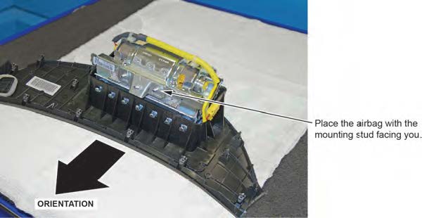
- Place the airbag, face-down, on a clean shop towel.
NOTE
The orientation of the airbag is critical because if the inflator is installed incorrectly, the harness will be too short when you reinstall the airbag.
- Visually inspect the airbag and the inflator for any unusual writing or Refer to IDENTIFYING COUNTERFEIT AIRBAGS.
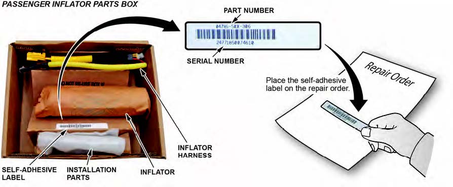
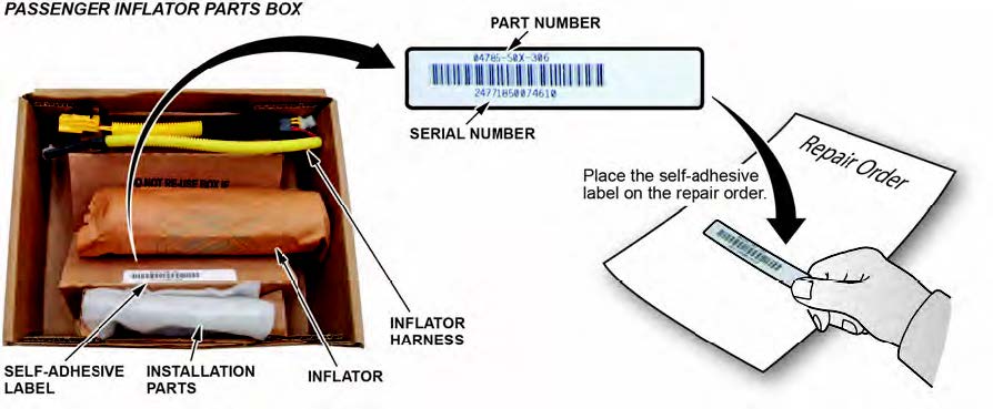
- Peel the label located inside the inflator box from its backing and attach it to the For the warranty claim to be paid, the replacement inflator part number that you received must be included in the warranty claim.
NOTES
- The replacement part number is printed on the top part of the label and the serial number is printed on the bottom. Make sure you attach the label to the RO and give it to the warranty clerk .
- There may also be a colored sticker located in the kit, ignore it because it is not used.
- Not all inflator kits have a label In those cases, write the serial number and part number from the side of the inflator box on the RO. The part number always starts with 047.
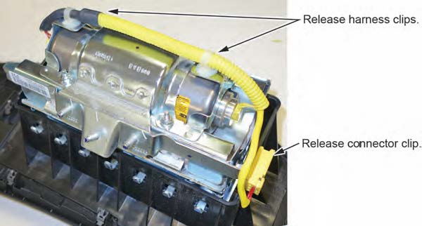
- Remove the harness from both ends of the inflator bracket.
- Short the yellow wires.
NOTES
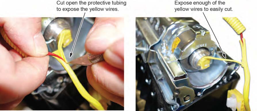
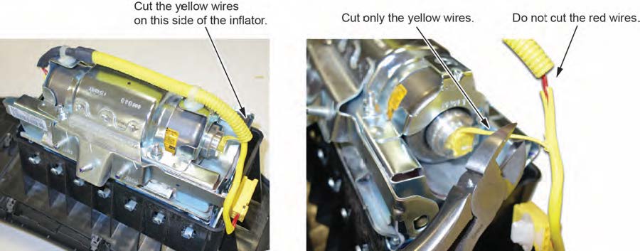
- You must cut and short the wires as indicated to prevent accidental deployment.
- Do not cut the red wires because the airbag connector shorts these inflator wires.
8.1 Cut 1–2 inches of the protective tube to access the yellow wires.
8.2 Cut the yellow wires as shown.
8.3 Strip away about 1 inch of the wire insulation, then twist the wires together.

8.4 Tape the twisted ends with electrical tape.
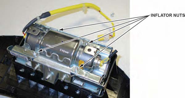
- Remove the four inflator nuts.
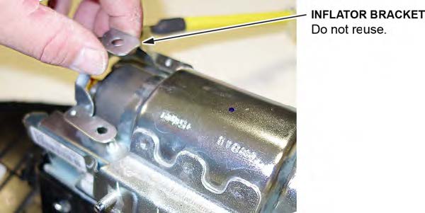
- Remove the inflator bracket.
NOTE
You can only remove one of the brackets, as the other is welded to the airbag housing.
- Remove the inflator by pushing it out.
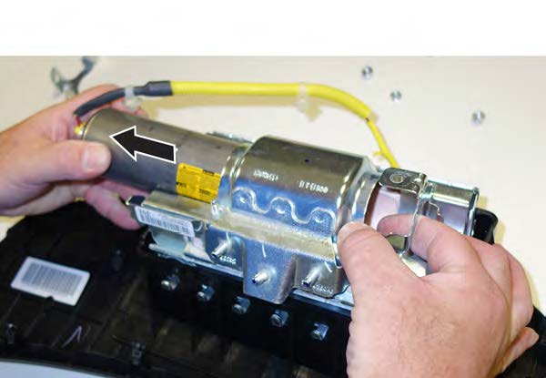
- Install the new inflator.
P/N 04790-TA0-407
12.1 One side of the inflator has a longer collar, a single tab, a plastic cutout, and a small flat spot on the The other side of the inflator has a shorter collar, two tabs, and a red dot. Make sure you insert the end with the shorter collar into the airbag first.
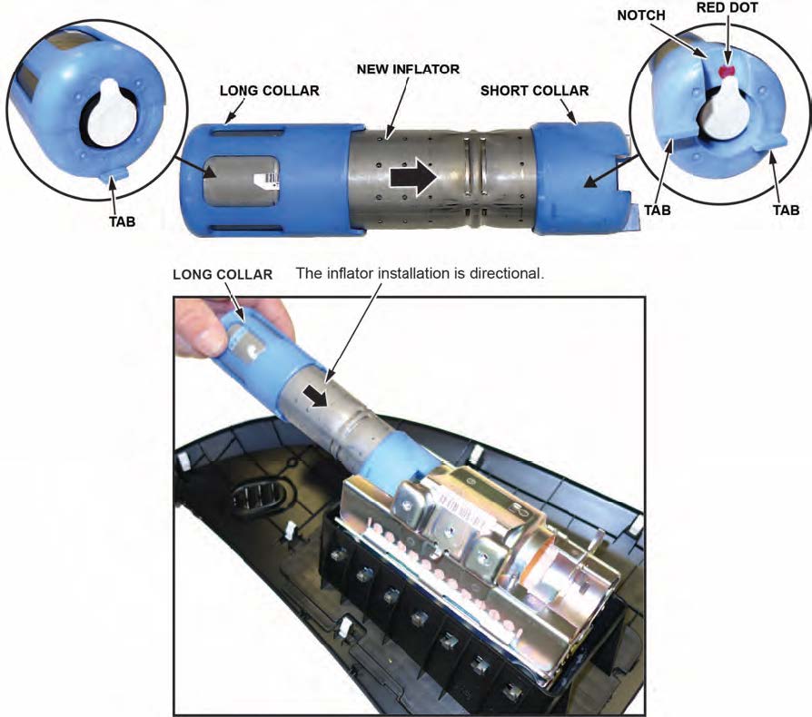
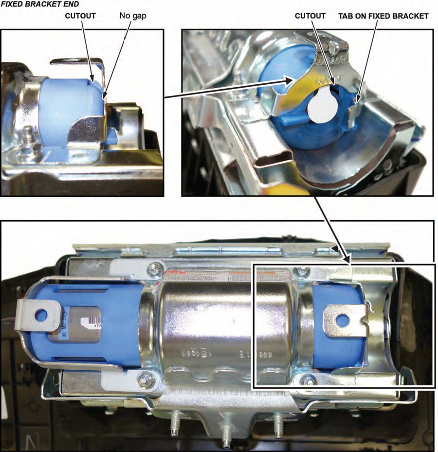
12.2 Slide the inflator in until the plastic cutout and the small flat spot align with the tab on the bracket. There should be no space or gap between the inflator and There is a red dot located on the fixed bracket side, which may be difficult to see because of the bracket.
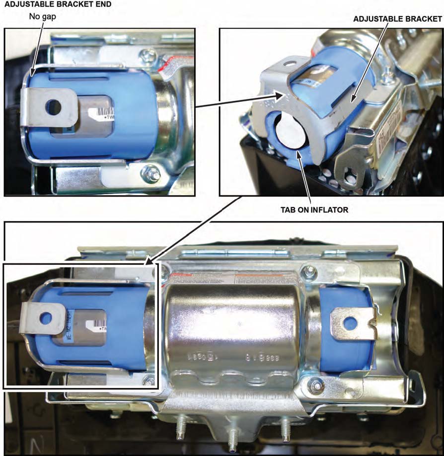
12.3 Install the bracket included in the kit onto the airbag module. There should be no space or gap between the inflator and bracket.
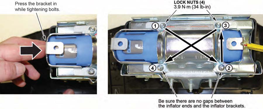
- Install the new 5 mm locknuts and torque them in sequence to 9 N•m (34 lb-in) .
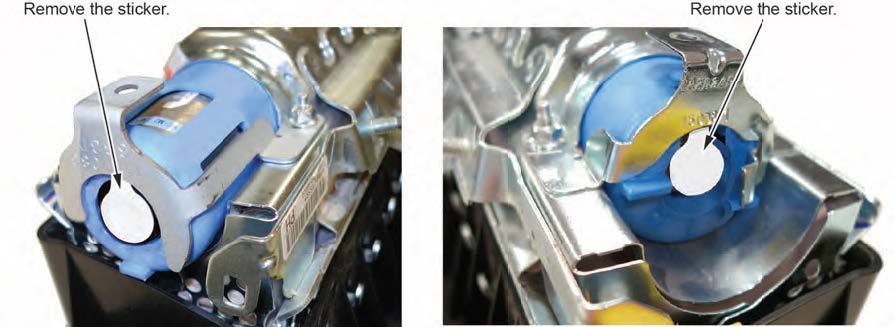
- Remove the stickers covering the terminals on both sides of the new inflator.
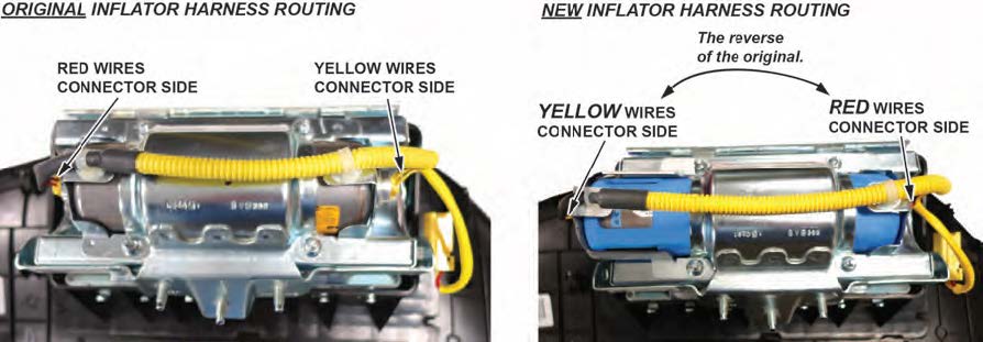
- Install the new inflator harness.
15.1 Make sure the airbag and harness are aligned as shown.
NOTES
- Make sure you have the orientation correct as shown below. If you connect the harness incorrectly, the harness cannot be removed, and you will not be able to reinstall the airbag because the harness will be too short.
- Connect the red wire connector to the short collar side of the inflator with the red dot.
- The red dot may be difficult to see because of the bracket.
15.2 Connect the two connectors. Align the “T” shape in the inflator harness connector with the T-shaped inflator connector, then press the connector into place.
NOTE
Connect the red harness to the side of the inflator with the red dot. The red dot may be difficult to see because of the bracket.
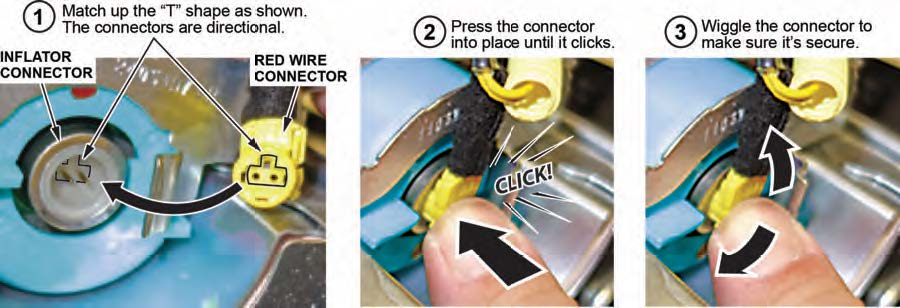
15.3 After you hear each connector click, wiggle it to make sure it is secure.
NOTE
If the connector is not properly aligned, it will come out.
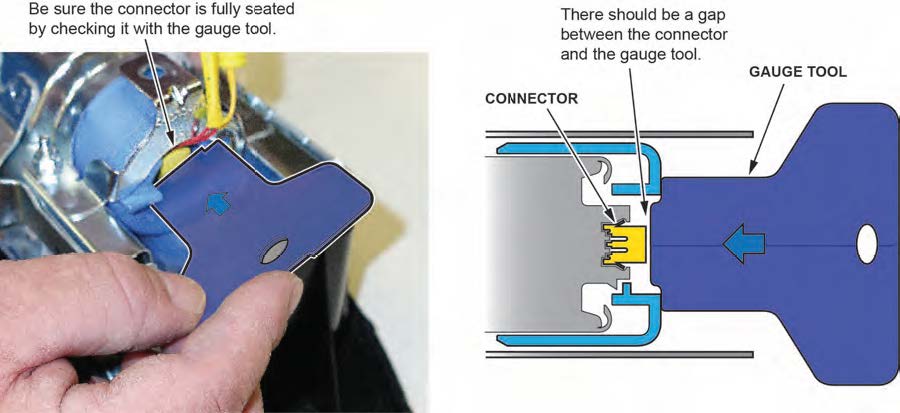
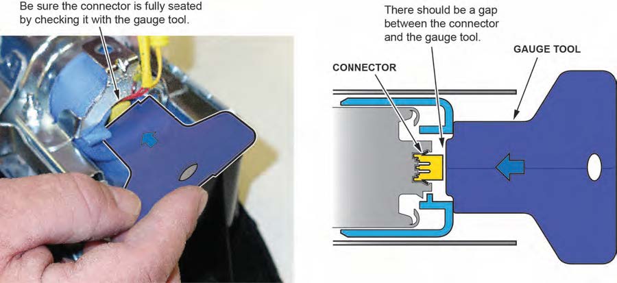
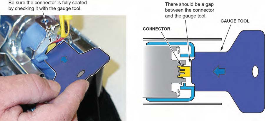
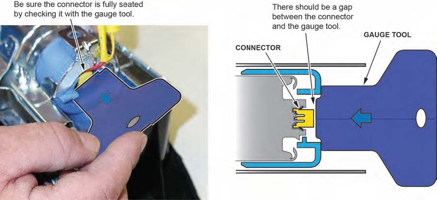
15.4 Make sure the connector is secure and in place by using the gauge tool. (PSPI6 Gauge Tool P/N: 070AJ- TA00A00 or 07AAJ-TA0AA00).
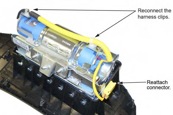
- Connect the harness to the inflator brackets as shown.
- Reinstall the passenger’s airbag into the vehicle and torque the new locknuts to 9.8 N•m (7.2 lb-ft) .
- Reconnect the battery negative cable and enter the anti-theft code for the audio and navigation system (if applicable), then enter the audio presets.
- Set the clock (for vehicles without navigation).
- Turn the ignition to ON and make sure the SRS indicator comes on for about 6 seconds, then goes off.
- Put the original inflator into the box the new one came Make sure there is no other hardware in the box because if the package rattles, it will not be accepted by the courier.
- Follow the shipping instructions outlined in PIB A15-0002 to return the undeployed inflator.
- Give your warranty clerk the RO that includes the replacement inflator serial number and replacement part For the warranty claim to be paid, the replacement inflator part number must be included in the warranty claim.
REPAIR PROCEDURE CIVIC/CIVIC CNG/CIVIC HYBRID
NOTES
- If the VIN status inquiry indicates that the vehicle is subject to any open safety recalls, including the driver’s airbag inflator, make sure to also complete those recall repairs before returning the vehicle to the customer. If you are unable to complete any open recall, advise the customer of the recall status and when the recall could be completed.
- Make sure you have the anti-theft code for the audio and navigation system (if applicable), then write down the frequencies for the radio’s preset buttons.
- Be careful not to damage any parts when replacing the inflator, and follow the procedure exactly.
- If, before removing the airbag, you suspect that it may be the incorrect airbag for the vehicle or a counterfeit, do not remove the airbag. Contact your DPSM for assistance.
- Make sure you have reviewed the SRS Precautions and Procedures in the service information before doing the REPAIR PROCEDURE.
- Turn the ignition switch to the ON (II) position and check if the SRS indicator comes on for about 6 seconds, then turns off.
- If the indicator comes on, then turns off after about 6 seconds, go to step 2.
- If the indicator does not come on, or if it stays on, contact your DPSM for assistance.
- Disconnect the battery negative cable and wait at least 3 minutes before continuing.
- Remove the front passenger’s airbag. Refer to the applicable vehicle’s service information.
- Place the airbag, face-down, on a clean shop towel.
NOTE
The orientation of the airbag is critical because if the inflator is installed incorrectly, the harness will be too short when you reinstall the airbag.
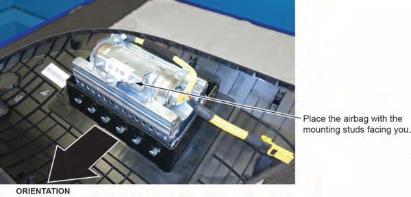
- Visually inspect the airbag and the inflator for any unusual writing or Refer to IDENTIFYING COUNTERFEIT AIRBAGS.
- Peel the label located inside the inflator box from its backing and attach it to the For the warranty claim to be paid, the replacement inflator part number that you received must be included in the warranty claim.
NOTES
- The replacement part number is printed on the top part of the label and the serial number is printed on the bottom. Make sure you attach the label to the RO and give it to the warranty clerk .
- There may also be a colored sticker located in the kit, ignore it because it is not used.
- Not all inflator kits have a label In those cases, write the serial number and part number from the side of the inflator box on the RO. The part number always starts with 047.
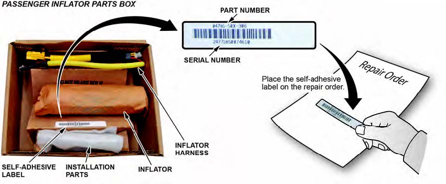
- Remove the harness from both ends of the inflator bracket.
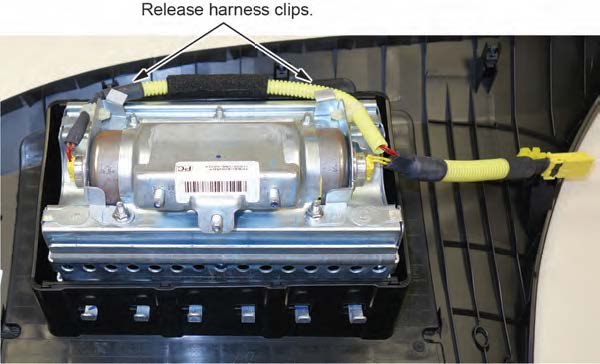
- Short the yellow wires.
NOTES
- You must cut and short the wires as indicated to prevent accidental deployment.
- Do not cut the red wires because the airbag connector shorts these inflator wires.
8.1 Cut 1–2 inches of the protective tube to access the yellow wires.
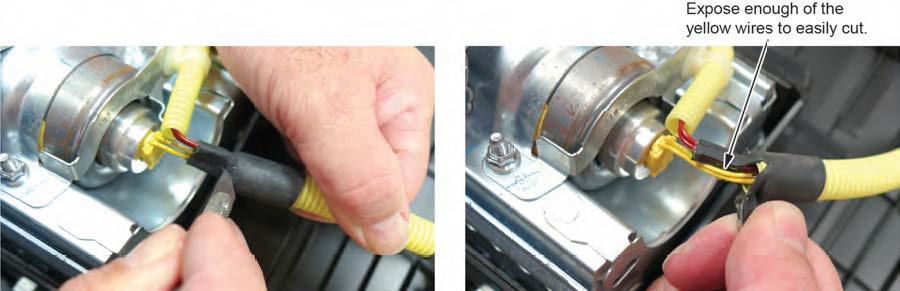
8.2 Cut the yellow wires as shown.
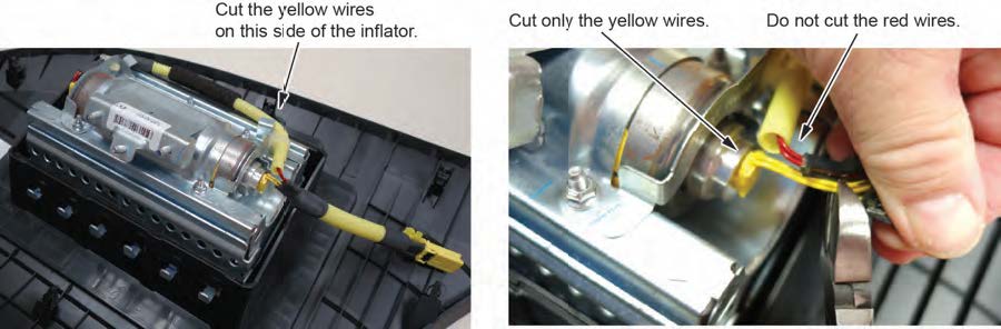
8.3 Strip away about 1 inch of the wire insulation, then twist the wires together.

8.4 Tape the twisted ends with electrical tape.
- Remove the four inflator nuts.
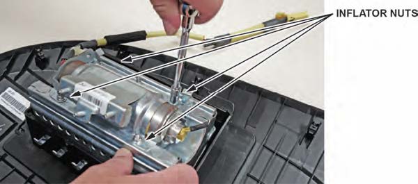
- Remove the inflator bracket.
NOTE
You can only remove one of the brackets, as the other is welded to the airbag housing.
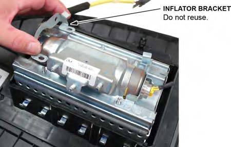
- Remove the inflator by pushing it out.
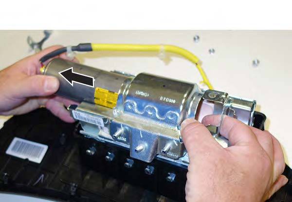
- Install the new inflator.
P/N 04790-SNA-407
12.1 One side of the inflator has a longer collar, a single tab, a plastic cutout, and a small flat spot on the The other side of the inflator has a shorter collar, two tabs, and a red dot. Make sure you insert the end with the shorter collar into the airbag first.
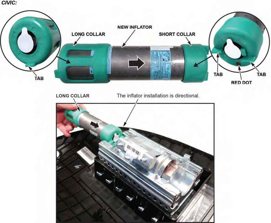
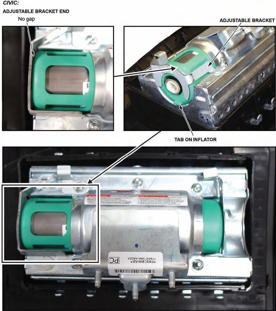
12.2 Slide the inflator in until the plastic collar contacts the bracket. The two tabs should align with the side of the airbag module and the metal tab as shown. There should be no space or gap between the inflator and bracket.
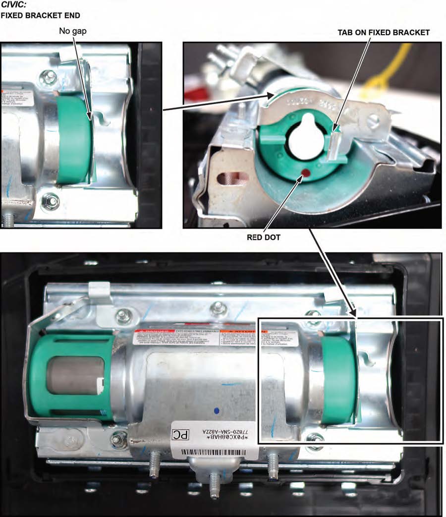
12.3 Install the new bracket included in the kit onto the airbag Check there is no space or gap between the inflator and bracket by pushing the bracket against the inflator.
NOTE
The bracket may have a little bit of play before you install the new nuts.
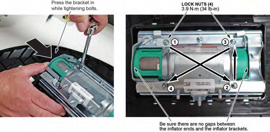
- Hold the bracket against the inflator, then install the new 5 mm locknuts and torque them in sequence to 4.0 N•m (34 lb-in).
NOTE
Make sure you push the bracket against the inflator to ensure there are no gaps between the brackets and inflator when torqueing the nuts.
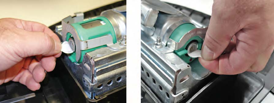
- Remove the stickers covering the terminals on both sides of the new inflator.
- Install the new inflator harness.
15.1 Make sure the airbag and harness are aligned as shown.
NOTES
- The replacement inflator harnesses have the wire colors in the opposite positions of the original harness. If you connect the harness incorrectly, the harness cannot be removed and you will not be able to reinstall the airbag because the harness will be too short.
- Connect the red wire connector to the side of the inflator with the red dot.
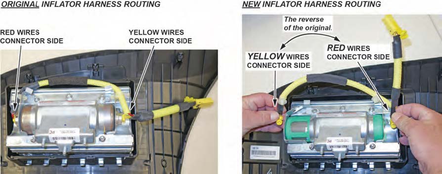
15.2 Connect the two connectors. Align the “T” shape in the inflator harness connector with the T-shaped inflator connector, then press the connector into place.
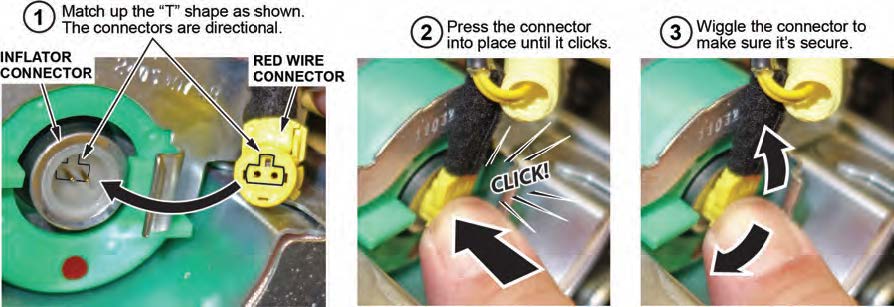
15.3 After you hear each connector click, wiggle it to make sure it is secure.
NOTE
If the connector is not properly aligned, it will come out.
- Connect the harness to the inflator brackets as shown.
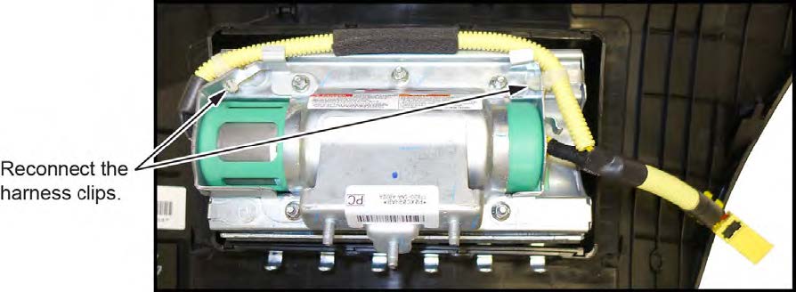
- Reinstall the passenger’s airbag into the vehicle and torque the new locknuts to 9.8 N•m (7.2 lb-ft) .
- Reconnect the battery negative cable and enter the anti-theft code for the audio and navigation system (if applicable), then enter the audio presets.
- Set the clock (for vehicles without navigation).
- Turn the ignition to ON and make sure the SRS indicator comes on for about 6 seconds, then goes off.
- Put the original inflator into the box the new one came Make sure there is no other hardware in the box because if the package rattles, it will not be accepted by the courier.
- Follow the shipping instructions outlined in PIB A15-0002 to return the undeployed inflator.
- Give your warranty clerk the RO that includes the replacement inflator serial number and replacement part For the warranty claim to be paid, the replacement inflator part number must be included in the warranty claim.
REPAIR PROCEDURE CR-V
NOTES
- If the VIN status inquiry indicates that the vehicle is subject to any open safety recalls, including the driver’s airbag inflator, make sure to also complete those recall repairs before returning the vehicle to the customer. If you are unable to complete any open recall, advise the customer of the recall status and when the recall could be completed.
- Make sure you have the anti-theft code for the audio and navigation system (if applicable), then write down the frequencies for the radio’s preset presets.
- Be careful not to damage any parts when replacing the inflator, and follow the procedure exactly.
- If, before removing the airbag, you suspect that it may be the incorrect airbag for the vehicle or a counterfeit, do not remove the airbag. Contact your DPSM for assistance.
- Make sure you have reviewed the SRS Precautions and Procedures in the service information before doing the REPAIR PROCEDURE.
- Turn the ignition switch to the ON (II) position and check if the SRS indicator comes on for about 6 seconds, then turns off.
- If the indicator comes on, then turns off after about 6 seconds, go to step 2.
- If the indicator does not come on, or if it stays on, contact your DPSM for assistance.
- Disconnect the battery negative cable and wait at least 3 minutes before continuing.
- Remove the front passenger’s airbag by referring to the service information.
- Place the airbag, face-down, on a clean shop towel.
NOTE
The orientation of the airbag is critical because if the inflator is installed incorrectly, the harness will be too short when you reinstall the airbag.
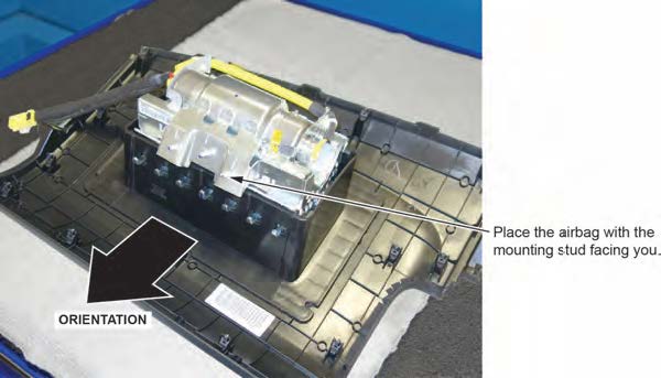
- Visually inspect the airbag and the inflator for any unusual writing or Refer to IDENTIFYING COUNTERFEIT AIRBAGS.
- Peel the label located inside the inflator box from its backing and attach it to the For the warranty claim to be paid, the replacement inflator part number that you received must be included in the warranty claim.
NOTES
- The replacement part number is printed on the top part of the label and the serial number is printed on the bottom. Make sure you attach the label to the RO and give it to the warranty clerk .
- There may also be a colored sticker located in the kit, ignore it because it is not used.
- Not all inflator kits have a label In those cases, write the serial number and part number from the side of the inflator box on the RO. The part number always starts with 047.
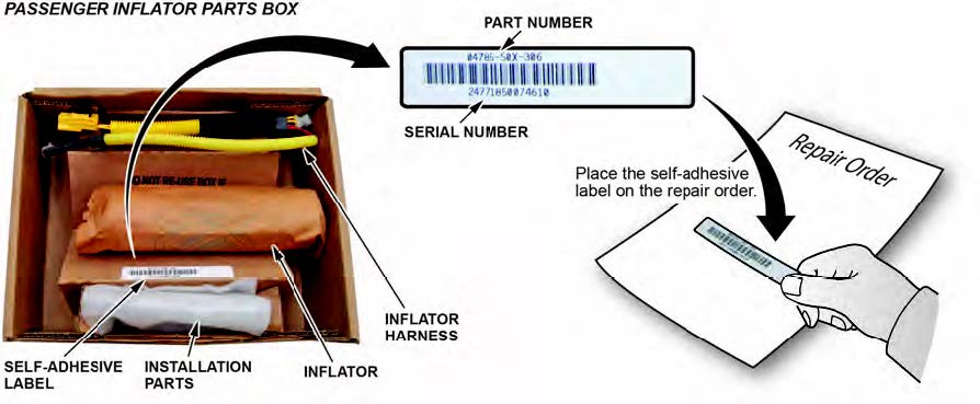
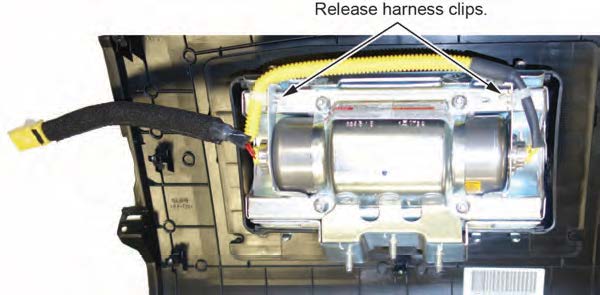
- Remove the harness from the inflator bracket.
- Short the yellow wires.
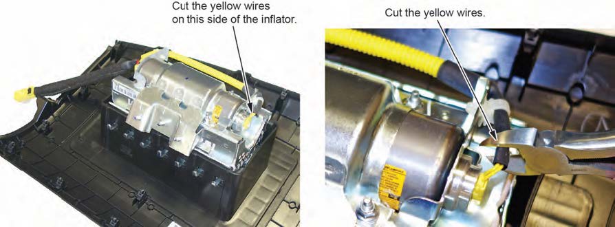
NOTES
- You must cut the yellow wires for inflator removal and short the yellow wires on the inflator side as indicated to prevent accidental deployment.
- Do not cut the red wires because the airbag connector shorts these inflator wires.
8.1 Cut the yellow wires as shown.
8.2 Strip away about 1 inch of the yellow wire insulation, then twist the wires together.

8.3 Tape the twisted ends with electrical tape.
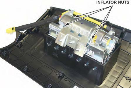
- Remove the four inflator nuts.
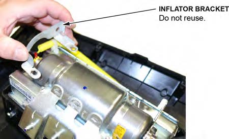
- Remove the inflator bracket.
NOTES
- You can only remove one of the brackets, as the other is welded to the airbag housing.
- Do not reuse the bracket; use the new one that came in the inflator kit.
- Remove the inflator by pulling it out.
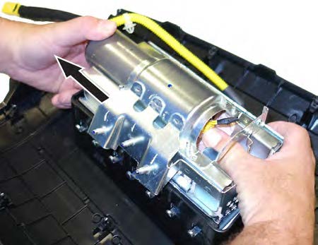
- Install the new inflator.
P/N 04790-SWA-407
12.1 One side of the inflator has a longer collar, a single tab, a plastic cutout, and a small flat spot on the The other side of the inflator has a shorter collar, two tabs, and a red dot. Make sure you insert the end with the shorter collar into the airbag first.
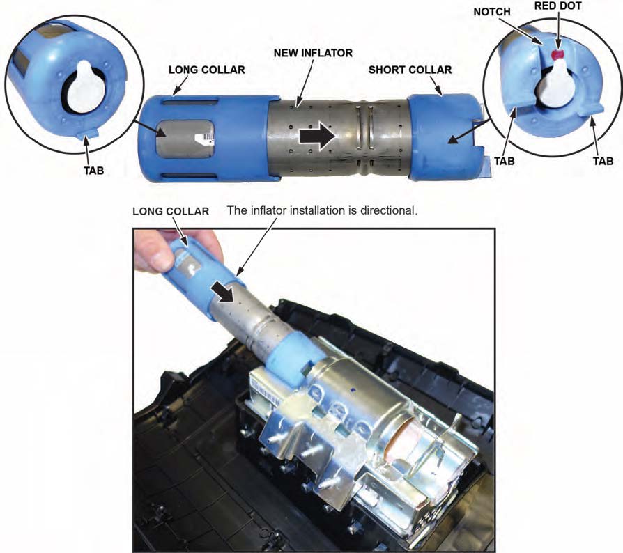
12.2 Slide the inflator in until the plastic collar contacts the bracket. The two tabs should align with the side of the airbag module and the metal tab as shown. There should be no space or gap between the inflator and bracket. There is a red dot located on the fixed bracket side, which may be difficult to see because of the bracket.
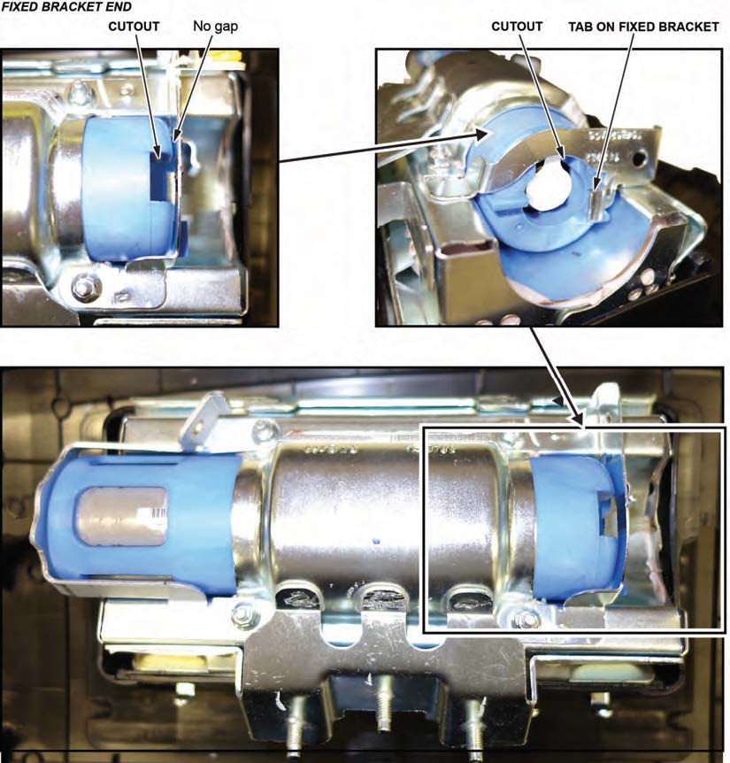
12.3 Install the bracket included in the kit onto the airbag Check there is no space or gap between the inflator and bracket by pushing the bracket against the inflator.
NOTE
The bracket may have a little bit of play before you install the new nuts.
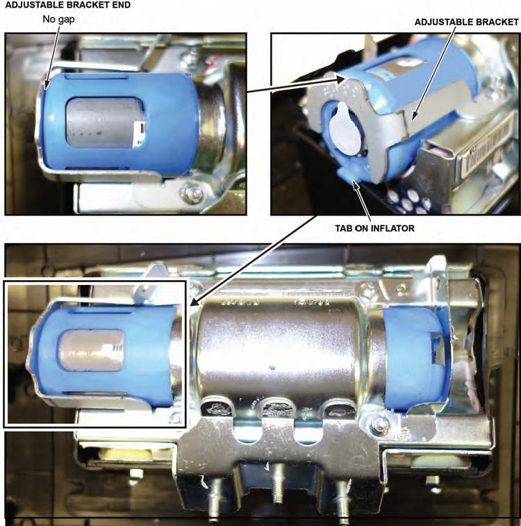
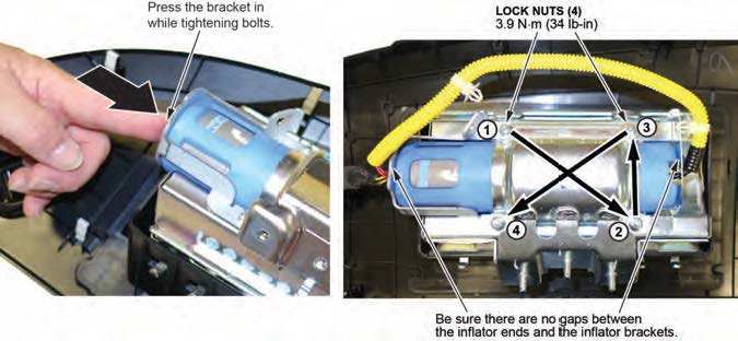
- Hold the bracket against the inflator, then install the four new 5 mm locknuts and torque them in sequence to 3.9 N•m (34 lb-in) .
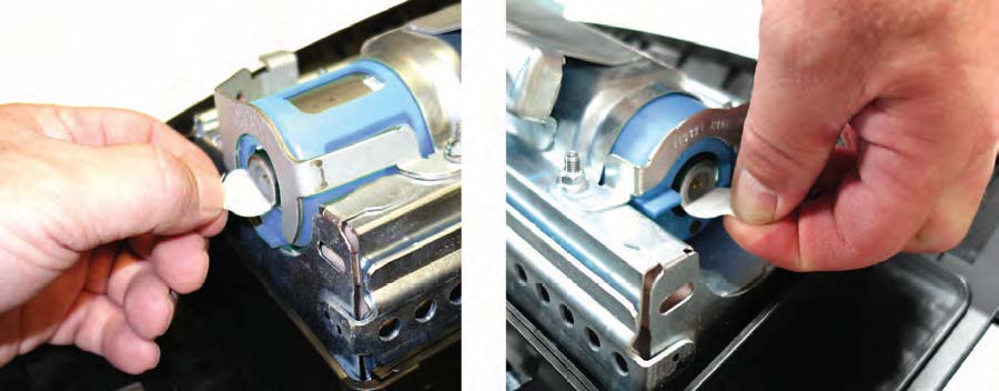
- Remove the stickers covering the terminals on both sides of the new inflator.
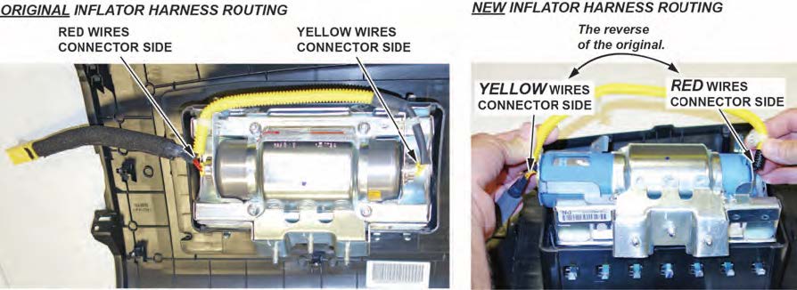
- Install the new inflator harness.
15.1 Make sure the airbag and harness are aligned as shown.
NOTES
- The replacement inflator harnesses have the wire colors in the opposite positions of the original harness. If you connect the harness incorrectly, the harness cannot be removed and you will not be able to reinstall the airbag because the harness will be too short.
- Connect the red wire connector to the short collar side of the inflator with the red dot.
- The red dot may be difficult to see because of the bracket.
15.2 Connect the red wire connector to the connector on the side with the short plastic Align the “T” shape in the inflator harness connector with the T-shaped inflator connector, then press the connector into place.
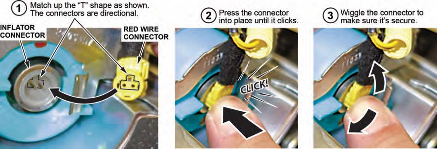
15.3 Connect the yellow wire connector to the connector on the side with the long plastic collar.
15.4 After you hear each connector click, wiggle it to make sure it is secure.
NOTE
If the connector is not properly aligned, it will come out.
15.5 Make sure the connector is secure and in place by using the gauge tool. (PSPI6 Gauge Tool P/N: 070AJ- TA00A00 or 07AAJ-TA0AA00).
- Connect the harness to the inflator brackets.
16.1 Insert the side without the shrink-wrap tubing first. Insert the harness at the third “valley” in the corrugated tube.
16.2 Insert the side of the harness with the shrink-wrap tubing into the inflator Make sure the harness is securely inserted and that it does not sag.
- Reconnect the battery negative cable and enter the anti-theft code for the audio and navigation system (if applicable), then enter the audio presets.
- Set the clock (for vehicles without navigation).
- Turn the ignition to ON and make sure the SRS indicator comes on for about 6 seconds, then goes off.
- Put the original inflator into the box the new one came Make sure there is no other hardware in the box because if the package rattles, it will not be accepted by the courier.
- Follow the shipping instructions outlined in PIB A15-0002 to return the undeployed inflator.
- Give your warranty clerk the RO that includes the replacement inflator serial number and replacement part For the warranty claim to be paid, the replacement inflator part number must be included in the warranty claim.
REPAIR PROCEDURE FIT AND FIT EV
NOTES
- If the VIN status inquiry indicates that the vehicle is subject to any open safety recalls, including the driver’s airbag inflator, make sure to also complete those recall repairs before returning the vehicle to the customer. If you are unable to complete any open recall, advise the customer of the recall status and when the recall could be completed.
- Make sure you have the anti-theft code for the audio and navigation system (if applicable), then write down the frequencies for the radio’s preset buttons.
- Be careful not to damage any parts when replacing the inflator, and follow the procedure exactly.
- If, before removing the airbag, you suspect that it may be the incorrect airbag for the vehicle or a counterfeit, do not remove the airbag. Contact your DPSM for assistance.
- Make sure you have reviewed the SRS Precautions and Procedures in the service information before doing the REPAIR PROCEDURE.
- Turn the ignition switch to the ON (II) position and check if the SRS indicator comes on for about 6 seconds, then turns off.
- If the indicator comes on, then turns off after about 6 seconds, go to step 2.
- If the indicator does not come on, or if it stays on, contact your DPSM for assistance.
- Disconnect the battery negative cable and wait at least 3 minutes before continuing.
- Remove the front passenger’s airbag by referring to the service information.
- Place the airbag, face-down, on a clean shop towel.
NOTES
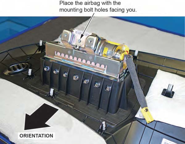
- The orientation of the airbag is critical because if the inflator is installed incorrectly, the harness will be too short when you reinstall the airbag.
- The Fit does not have mounting studs. It is secured in the vehicle with bolts, so make sure the mounting bolt holes are facing you.
- Visually inspect the airbag and the inflator for any unusual writing or Refer to IDENTIFYING COUNTERFEIT AIRBAGS.
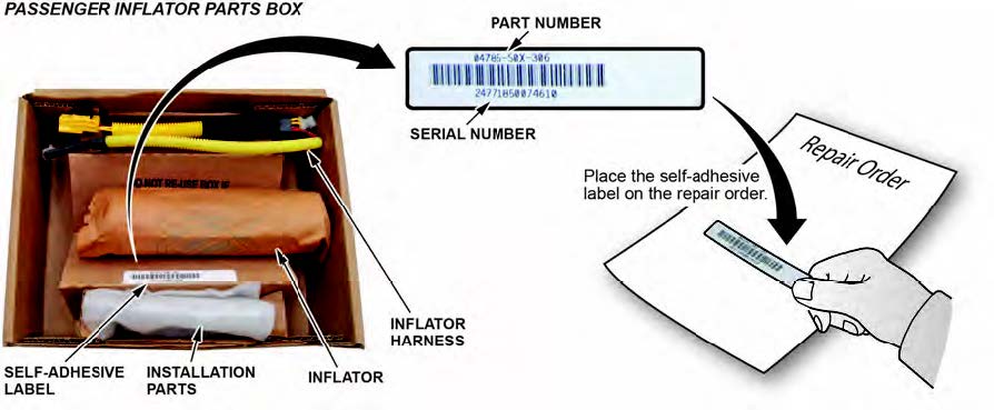
- Peel the label located inside the inflator box from its backing and attach it to the For the warranty claim to be paid, the replacement inflator part number that you received must be included in the warranty claim.
NOTES
- The replacement part number is printed on the top part of the label and the serial number is printed on the bottom. Make sure you attach the label to the RO and give it to the warranty clerk .
- There may also be a colored sticker located in the kit, ignore it because it is not used.
- Not all inflator kits have a label In those cases, write the serial number and part number from the side of the inflator box on the RO. The part number always starts with 047.
- Remove the harness from the inflator bracket.
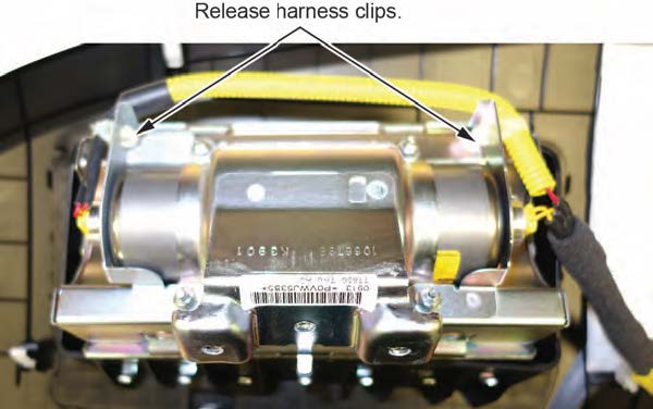
- Short the yellow wires.
NOTES
- You must cut the yellow wires for inflator removal and short the yellow wires on the inflator side as indicated to prevent accidental deployment.
- Do not cut the red wires because the airbag connector shorts these inflator wires.
- There is glue securing the black insulation to the yellow Be careful not to cut the wires when removing the insulation.
8.1 Cut 1–2 inches of the corrugated tube to access the yellow wires.
8.2 Cut the yellow wires as shown.
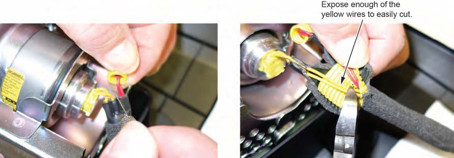
8.3 Strip away about 1 inch of the yellow wire insulation, then twist the wires together.

8.4 Tape the twisted ends with electrical tape.
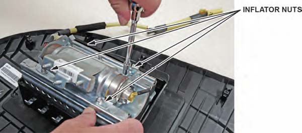
- Remove the four inflator nuts.
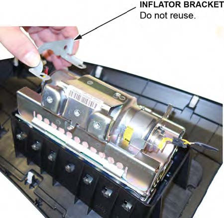
- Remove the inflator bracket.
NOTES
- You can only remove one of the brackets, as the other is welded to the airbag housing.
- Do not reuse the bracket; use the new one that came in the inflator kit.
- Remove the inflator by pulling it out.
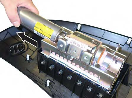
- Install the new inflator.
P/N 04790-TK6-407
12.1 One side of the inflator has a longer collar, a single tab, a plastic cutout, and a small flat spot on the The other side of the inflator has a shorter collar, two tabs, and a red dot. Make sure you insert the end with the shorter collar into the airbag first.
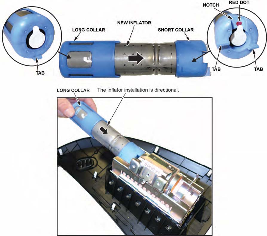
12.2 Slide the inflator in until the plastic collar contacts the bracket. The two tabs should align with the side of the airbag module and the metal tab as shown. There should be no space or gap between the inflator and bracket.
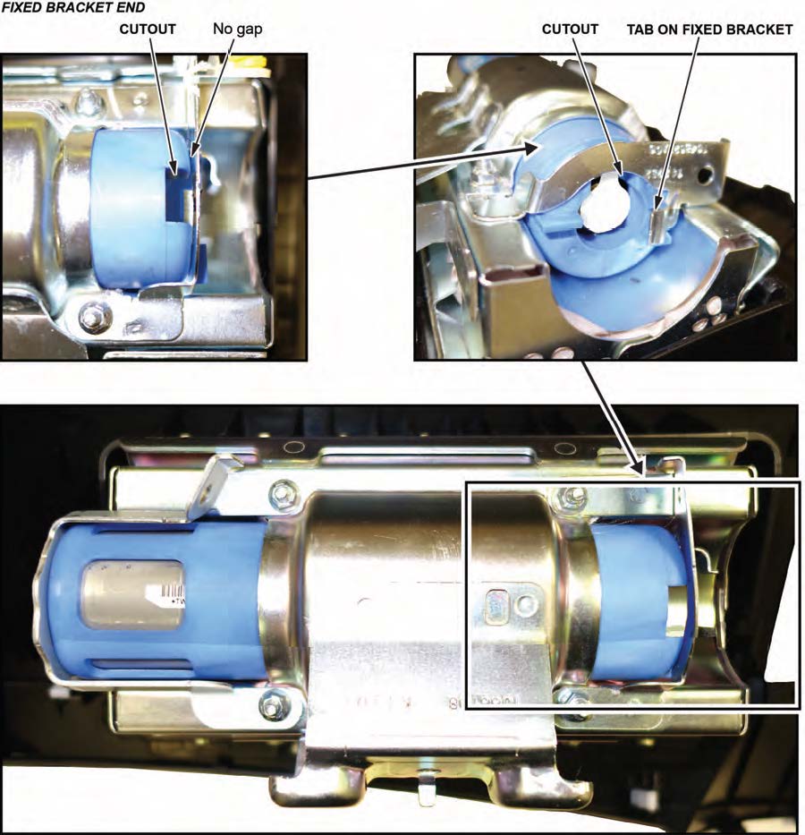
12.3 Install the bracket included in the kit onto the airbag Check there is no space or gap between the inflator and bracket by pushing the bracket against the inflator.
NOTE
The bracket may have a little bit of play before you install the new nuts.
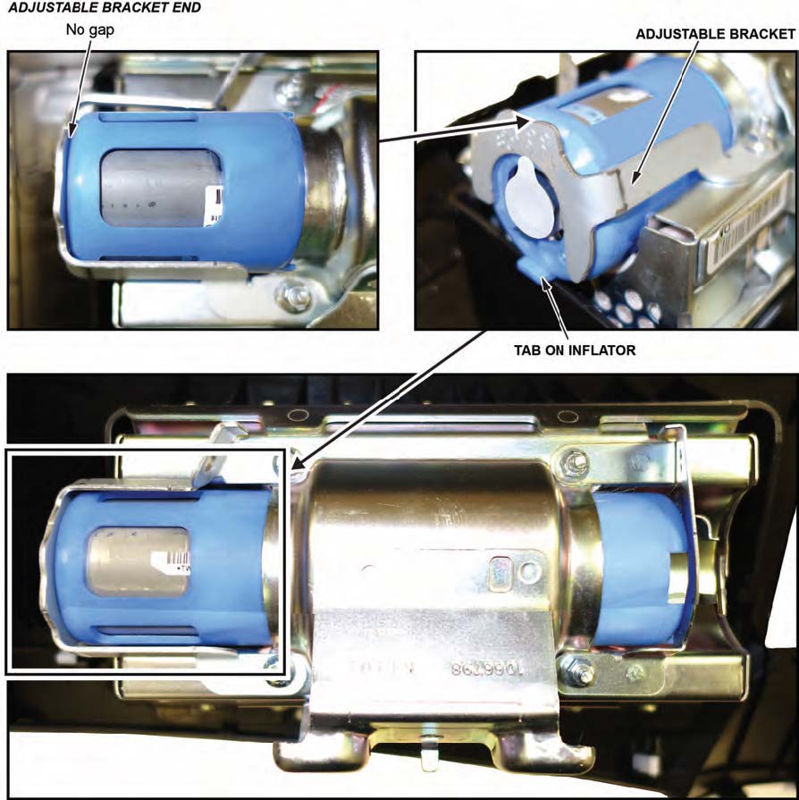
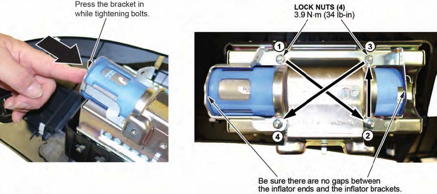
- Hold the bracket against the inflator, then install the new 5 mm locknuts and torque them in sequence to 3.9 N•m (34 lb-in) .
NOTE
Make sure you push the bracket against the inflator to ensure there are no gaps between the brackets and inflator when torqueing the nuts.
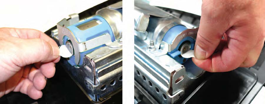
- Remove the stickers covering the terminals on both sides of the new inflator.
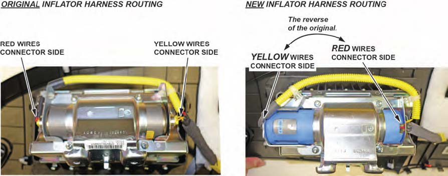
- Install the new inflator harness.
15.1 Make sure the airbag and harness are aligned as shown.
NOTES
- The replacement inflator harnesses have the wire colors in the opposite positions of the original harness. If you connect the harness incorrectly, the harness cannot be removed and you will not be able to reinstall the airbag because the harness will be too short.
- Connect the red wire connector to the short collar side of the inflator with the red dot.
- The red dot may be difficult to see because of the bracket.
15.2 Connect the red wire connector to the connector on the side with the short plastic Align the “T” shape in the inflator harness connector with the T-shaped inflator connector, then press the connector into place.
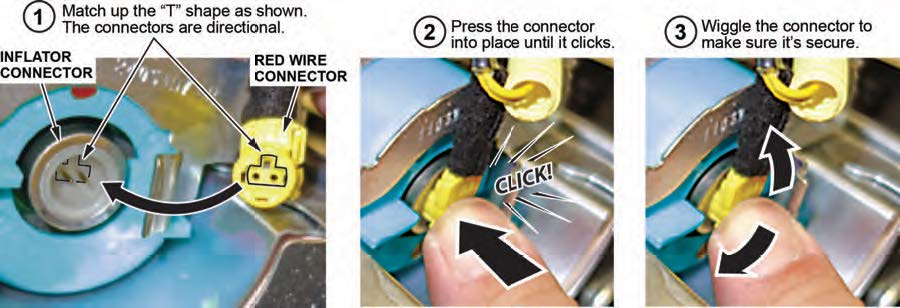
15.3 Connect the yellow wire connector to the connector on the side with the long plastic collar.
15.4 After you hear each connector click, wiggle it to make sure it is secure.
NOTE
If the connector is not properly aligned, it will come out.
15.5 Make sure the connector is secure and in place by using the gauge tool. (PSPI6 Gauge Tool P/N: 070AJ- TA00A00 or 07AAJ-TA0AA00).
- Connect the harness to the inflator brackets.
- Reinstall the passenger’s airbag into the vehicle and torque the new locknuts to 9.8 N•m (7.2 lb-ft).
- Reconnect the battery negative cable and enter the anti-theft code for the audio and navigation system (if applicable), then enter the audio presets.
- Set the clock (for vehicles without navigation).
- Turn the ignition to ON and make sure the SRS indicator comes on for about 6 seconds, then goes off.
- Put the original inflator into the box the new one came Make sure there is no other hardware in the box because if the package rattles, it will not be accepted by the courier.
- Follow the shipping instructions outlined in PIB A15-0002 to return the undeployed inflator.
- Give your warranty clerk the RO that includes the replacement inflator serial number and replacement part For the warranty claim to be paid, the replacement inflator part number must be included in the warranty claim.
REPAIR PROCEDURE INSIGHT
NOTES
- If the VIN status inquiry indicates that the vehicle is subject to any open safety recalls, including the driver’s airbag inflator, make sure to also complete those recall repairs before returning the vehicle to the customer. If you are unable to complete any open recall, advise the customer of the recall status and when the recall could be completed.
- Make sure you have the anti-theft code for the audio and navigation system (if applicable), then write down the frequencies for the radio’s preset buttons.
- Be careful not to damage any parts when replacing the inflator, and follow the procedure exactly.
- If, before removing the airbag, you suspect that it may be the incorrect airbag for the vehicle or a counterfeit, do not remove the airbag. Contact your DPSM for assistance.
- Make sure you have reviewed the SRS Precautions and Procedures in the service information before doing the REPAIR PROCEDURE.
- Turn the ignition switch to the ON (II) position and check if the SRS indicator comes on for about 6 seconds, then turns off.
- If the indicator comes on, then turns off after about 6 seconds, go to step 2.
- If the indicator does not come on, or if it stays on, contact your DPSM for assistance.
- Disconnect the battery negative cable and wait at least 3 minutes before continuing.
- Remove the front passenger’s
3.1 While holding the glove box, release the glove box stops on each side from the dashboard by pushing them in, then lower the glove airbag.
3.2 Disconnect the dashboard wire harness 4P connector from the front passenger’s airbag.
3.3 Remove the two mounting nuts from the bracket.
3.4 Remove the front passenger’s airbag assembly from the dashboard.
NOTES
- The front passenger’s lid has pawls on each side that attach it to the dashboard.
- Take care not to scratch the dashboard or the front passenger’s lid.
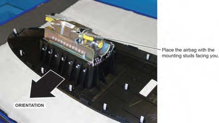
- Place the airbag, face-down, on a clean shop towel.
NOTE
The orientation of the airbag is critical because if the inflator is installed incorrectly, the harness will be too short when you reinstall the airbag.
- Visually inspect the airbag and the inflator for any unusual writing or Refer to IDENTIFYING COUNTERFEIT AIRBAGS.
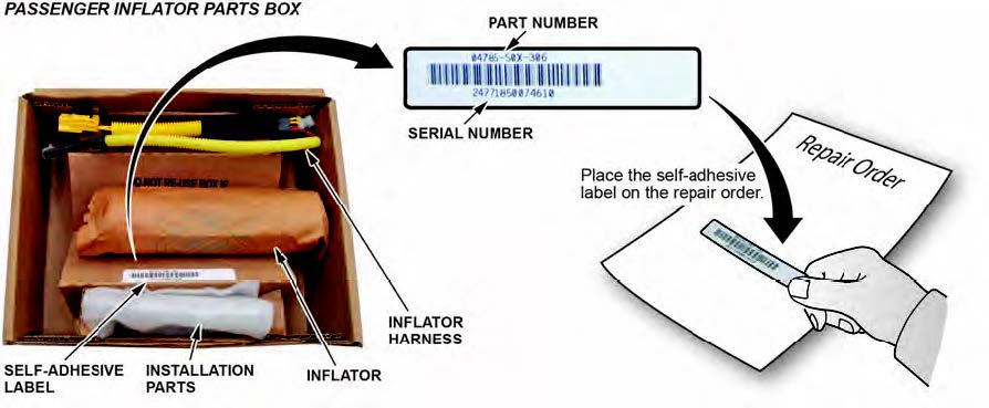
- Peel the label located inside the inflator box from its backing and attach it to the For the warranty claim to be paid, the replacement inflator part number that you received must be included in the warranty claim.
NOTES
- The replacement part number is printed on the top part of the label and the serial number is printed on the bottom. Make sure you attach the label to the RO and give it to the warranty clerk .
- There may also be a colored sticker located in the kit, ignore it because it is not used.
- Not all inflator kits have a label In those cases, write the serial number and part number from the side of the inflator box on the RO. The part number always starts with 047.
- Remove the harness from the inflator bracket.
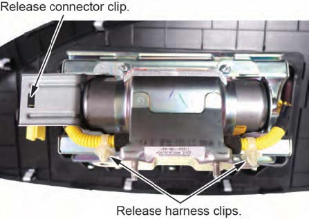
- Short the yellow wires.
NOTES
- You must cut the yellow wires for inflator removal and short the yellow wires on the inflator side as indicated to prevent accidental deployment.
- Do not cut the red wires because the airbag connector shorts these inflator wires.
8.1 Cut the yellow wires next to the white harness clip as shown.
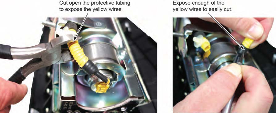
8.2 Strip away about 1 inch of the yellow wire insulation, then twist the wires together.

8.3 Tape the twisted ends with electrical tape.
- Remove the four inflator nuts.
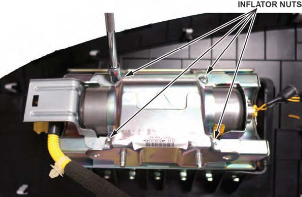
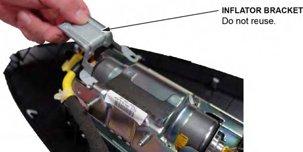
- Remove the inflator bracket.
NOTES
- You can only remove one of the brackets, as the other is welded to the airbag housing.
- Do not reuse the bracket; use the new one that came in the inflator kit.
- Remove the inflator by pulling it out.
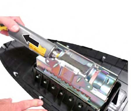
- Install the new inflator.
P/N 04790-TM8-407
12.1 One side of the inflator has a longer collar, a single tab, a plastic cutout, and a small flat spot on the The other side of the inflator has a shorter collar, two tabs, and a red dot. Make sure you insert the end with the shorter collar into the airbag first.
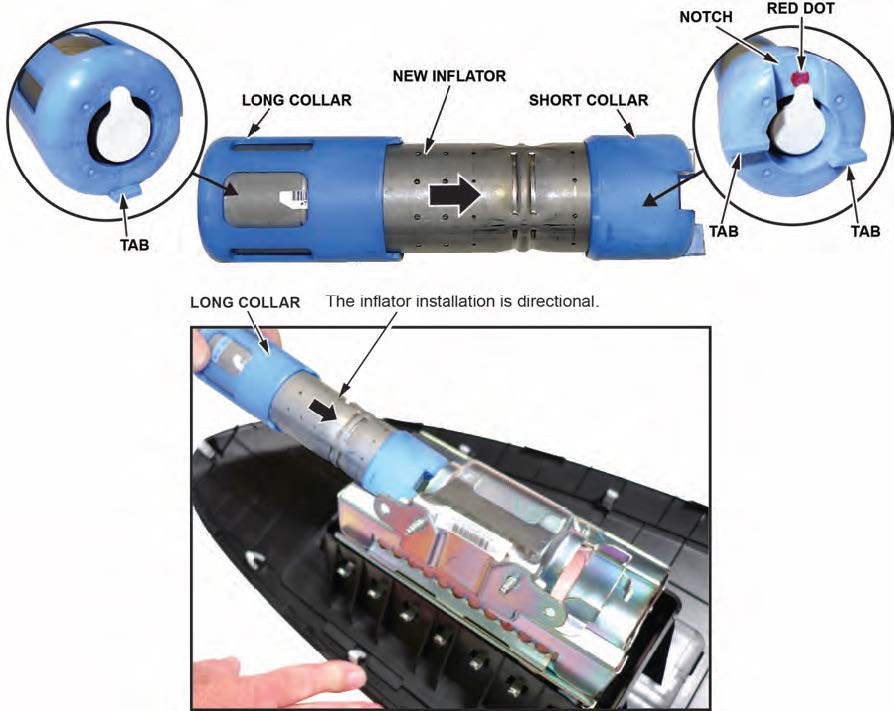
12.2 Slide the inflator in until the plastic collar contacts the bracket. The two tabs should align with the side of the airbag module and the metal tab as shown. There should be no space or gap between the inflator and bracket.
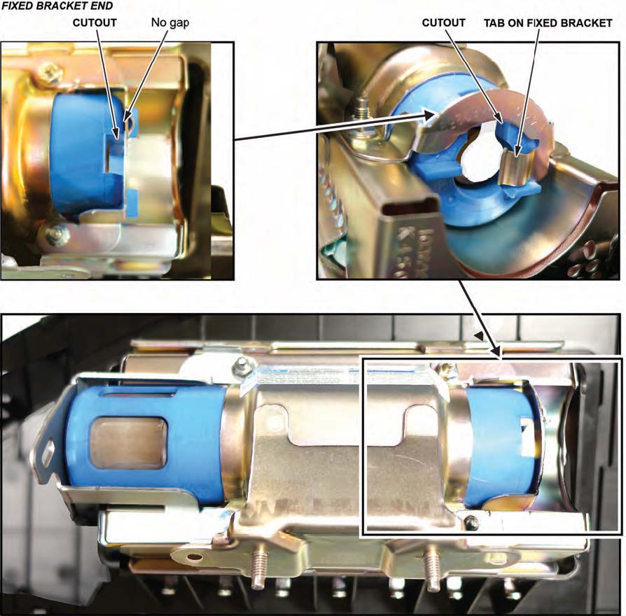
12.3 Install the bracket included in the kit onto the airbag Check there is no space or gap between the inflator and bracket by pushing the bracket against the inflator.
NOTE
The bracket may have a little bit of play before you install the new nuts.
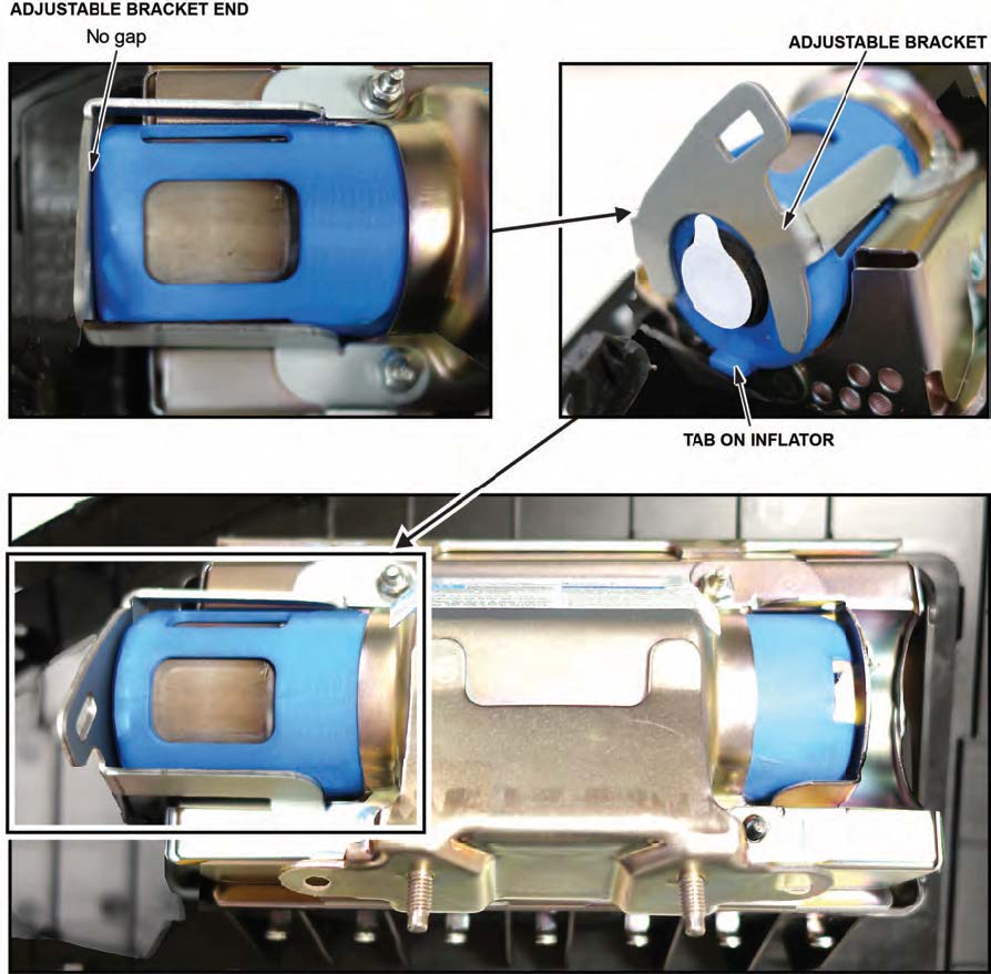
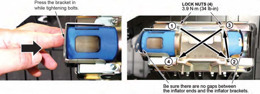
- Hold the bracket against the inflator, then install the new 5 mm locknuts and torque them in sequence to 4.0 N•m (34 lb-in) .
NOTE
Make sure you push the bracket against the inflator to ensure there are no gaps between the brackets and inflator when torqueing the nuts.
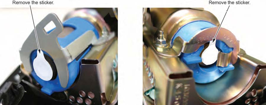
- Remove the stickers covering the terminals on both sides of the new inflator.
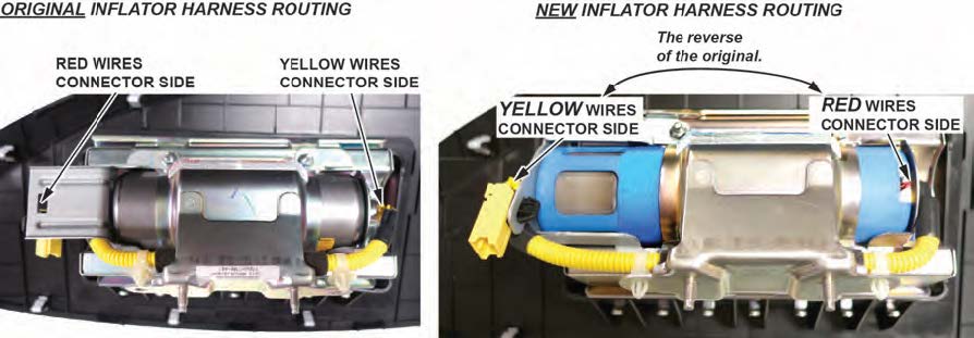
- Install the new inflator harness.
15.1 Make sure the airbag and harness are aligned as shown.
NOTES
- The replacement inflator harnesses have the wire colors in the opposite positions of the original harness. If you connect the harness incorrectly, the harness cannot be removed and you will not be able to reinstall the airbag because the harness will be too short.
- Connect the red wire connector to the short collar side of the inflator with the red dot.
- The red dot may be difficult to see because of the bracket.
15.2 Connect the red wire connector to the connector on the side with the short plastic Align the “T” shape in the inflator harness connector with the T-shaped inflator connector, then press the connector into place.
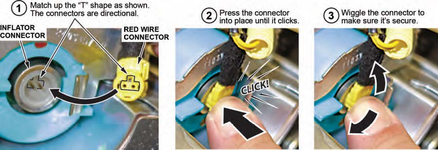
15.3 Connect the yellow wire connector to the connector on the side with the long plastic collar.
15.4 After you hear each connector click, wiggle it to make sure it is secure.
NOTE
If the connector is not properly aligned, it will come out.
15.5 Make sure the connector is secure and in place by using the gauge tool. (PSPI6 Gauge Tool P/N: 070AJ- TA00A00 or 07AAJ-TA0AA00).
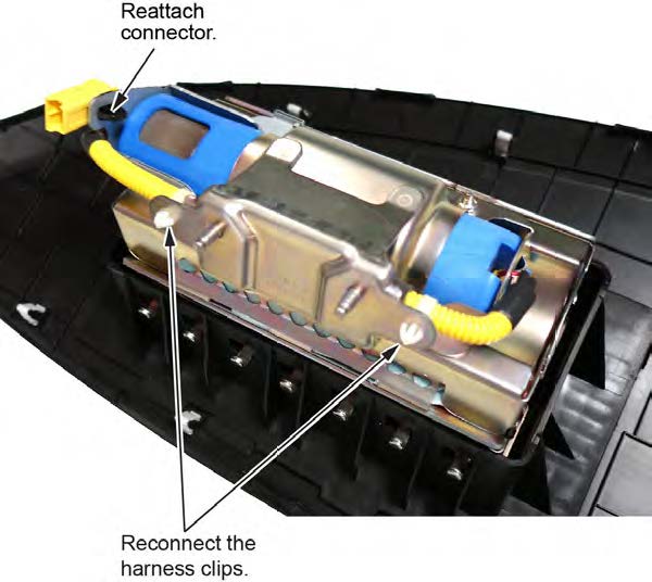
- Connect the harness to the inflator brackets.
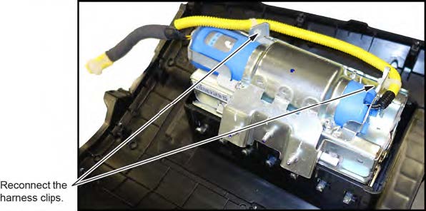
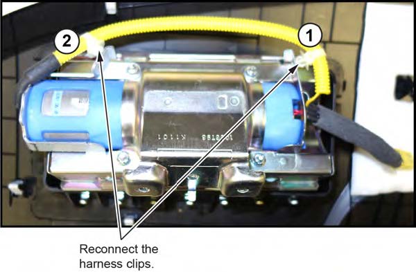
16.1 Connect the harness clips as shown.
16.2 Attach the 4-pin connector to the bracket as shown.
- Reinstall the passenger’s airbag into the vehicle and torque the new locknuts to 9.8 N•m (7.2 lb-ft).
- Reconnect the battery negative cable and enter the anti-theft code for the audio and navigation system (if applicable), then enter the audio presets.
- Set the clock (for vehicles without navigation).
- Turn the ignition to ON and make sure the SRS indicator comes on for about 6 seconds, then goes off.
- Put the original inflator into the box the new one came Make sure there is no other hardware in the box because if the package rattles, it will not be accepted by the courier.
- Follow the shipping instructions outlined in PIB A15-0002 to return the undeployed inflator.
- Give your warranty clerk the RO that includes the replacement inflator serial number and replacement part For the warranty claim to be paid, the replacement inflator part number must be included in the warranty claim.
REPAIR PROCEDURE PILOT
NOTES
- If the VIN status inquiry indicates that the vehicle is subject to any open safety recalls, including the driver’s airbag inflator, make sure to also complete those recall repairs before returning the vehicle to the customer. If you are unable to complete any open recall, advise the customer of the recall status and when the recall could be completed.
- Make sure you have the anti-theft code for the audio and navigation system (if applicable), then write down the frequencies for the radio’s preset buttons.
- Be careful not to damage any parts when replacing the inflator, and follow the procedure exactly.
- If, before removing the airbag, you suspect that it may be the incorrect airbag for the vehicle or a counterfeit, do not remove the airbag. Contact your DPSM for assistance.
- Make sure you have reviewed the SRS Precautions and Procedures in the service information before doing the REPAIR PROCEDURE.
- Turn the ignition switch to the ON (II) position and check if the SRS indicator comes on for about 6 seconds, then turns off.
- If the indicator comes on, then turns off after about 6 seconds, go to step 2.
- If the indicator does not come on, or if it stays on, contact your DPSM for assistance.
- Disconnect the battery negative cable and wait at least 3 minutes before continuing.
- Remove the front passenger’s airbag.
3.1 Remove the front passenger’s dashboard trim by referring to the service information.
3.2 Disconnect the front passenger’s airbag 4P connector from the dashboard wire harness.
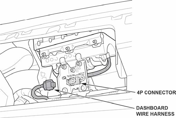
3.3 Remove the mounting nuts and bolts to remove the bracket.
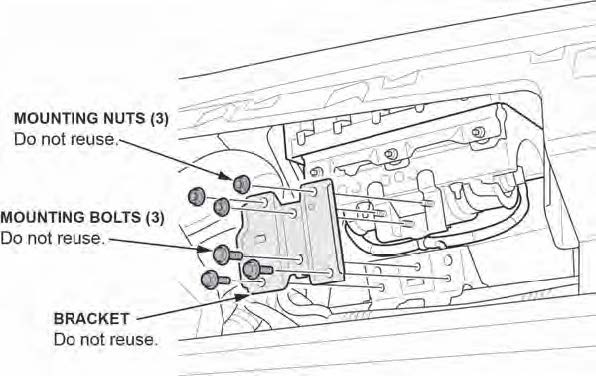
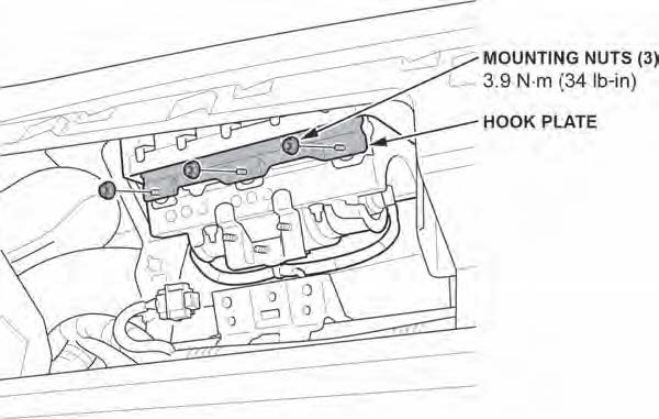
3.4 Remove the mounting nuts from the hook plate.
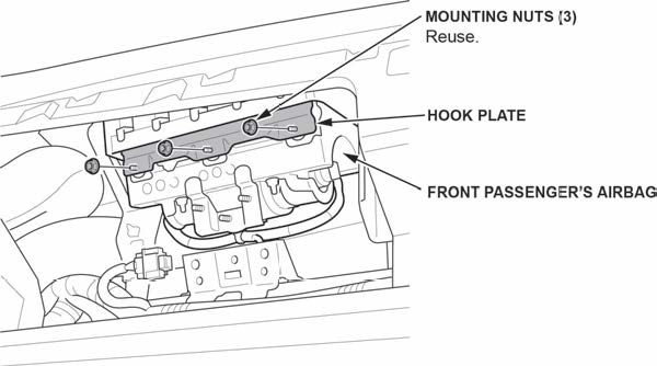
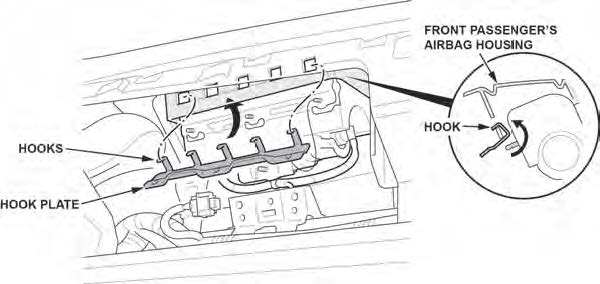
3.5 Release the hooks on the hook plate from the front passenger’s airbag housing and remove the hook plate.
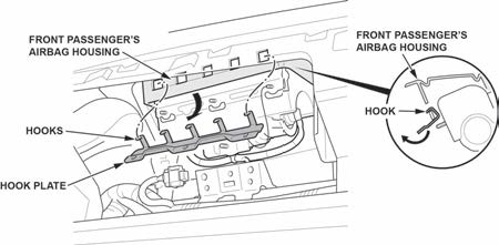
3.6 Remove the front passenger’s airbag.
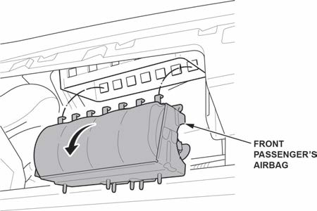
- Place the airbag, face-down, on a clean shop towel.
NOTE
The orientation of the airbag is critical because if the inflator is installed incorrectly, the harness will be too short when you reinstall the airbag.
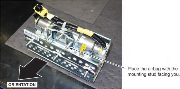
- Visually inspect the airbag and the inflator for any unusual writing or Refer to IDENTIFYING COUNTERFEIT AIRBAGS.
- Peel the label located inside the inflator box from its backing and attach it to the For the warranty claim to be paid, the replacement inflator part number that you received must be included in the warranty claim.
NOTES
- The replacement part number is printed on the top part of the label and the serial number is printed on the bottom. Make sure you attach the label to the RO and give it to the warranty clerk .
- There may also be a colored sticker located in the kit, ignore it because it is not used.
- Not all inflator kits have a label In those cases, write the serial number and part number from the side of the inflator box on the RO. The part number always starts with 047.
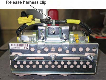
- Remove the harness from the inflator bracket.
- Short the yellow wires.
NOTES
- You must cut the yellow wires for inflator removal and short the yellow wires on the inflator side as indicated to prevent accidental deployment.
- Do not cut the red wires because the airbag connector shorts these inflator wires.
- There is glue securing the black insulation to the yellow Be careful not to cut the wires when removing the insulation.
8.1 Cut the yellow wires as shown.
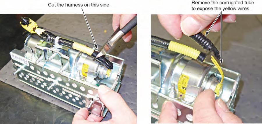
8.2 Strip away about 1 inch of the yellow wire insulation, then twist the wires together.

8.3 Tape the twisted ends with electrical tape.
- Remove the four inflator nuts.
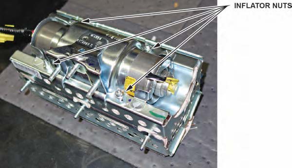
- Remove the inflator bracket.
NOTES
- You can only remove one of the brackets, as the other is welded to the airbag housing.
- Do not reuse the bracket; use the new one that came in the inflator kit.
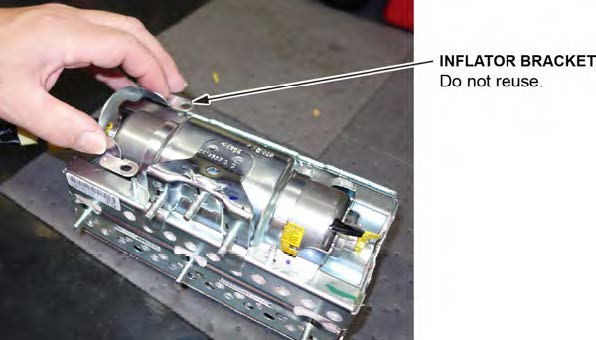
- Remove the inflator by pulling it out.
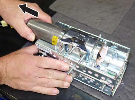
- Install the new inflator.
P/N 04790-SZA-407
12.1 One side of the inflator has a longer collar, a single tab, a plastic cutout, and a small flat spot on the The other side of the inflator has a shorter collar, two tabs, and a red dot. Make sure you insert the end with the shorter collar into the airbag first.
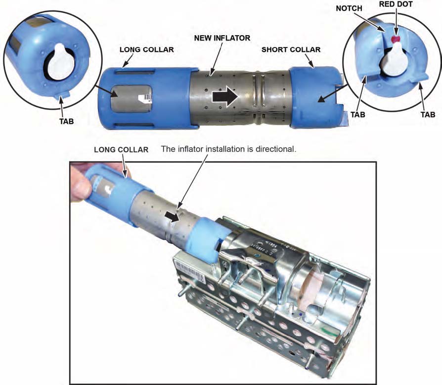
12.2 Slide the inflator in until the plastic collar contacts the bracket. The two tabs should align with the side of the airbag module and the metal tab as shown. There should be no space or gap between the inflator and bracket.
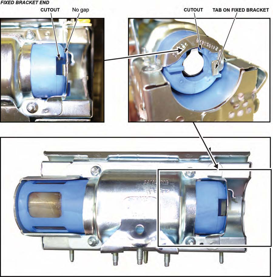
12.3 Install the bracket included in the kit onto the airbag Check there is no space or gap between the inflator and bracket by pushing the bracket against the inflator.
NOTE
The bracket may have a little bit of play before you install the new nuts.
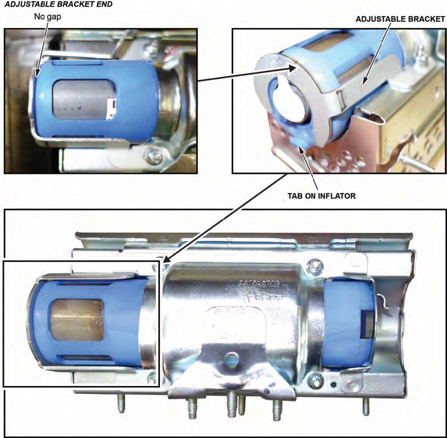
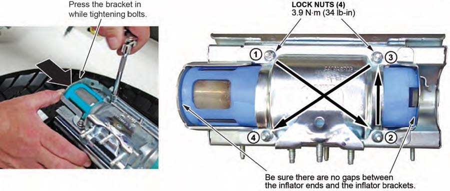
- Hold the bracket against the inflator, then install the new 5 mm locknuts and torque them in sequence to 4.0 N•m (34 lb-in) .
NOTE
Make sure you push the bracket against the inflator to ensure there are no gaps between the brackets and inflator when torqueing the nuts.
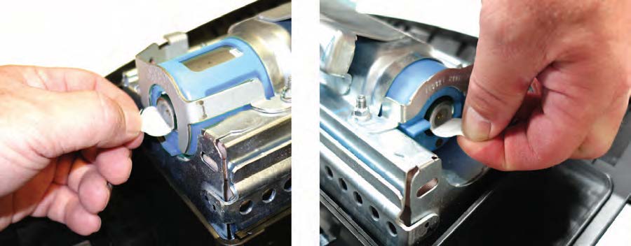
- Remove the stickers covering the terminals on both sides of the new inflator.
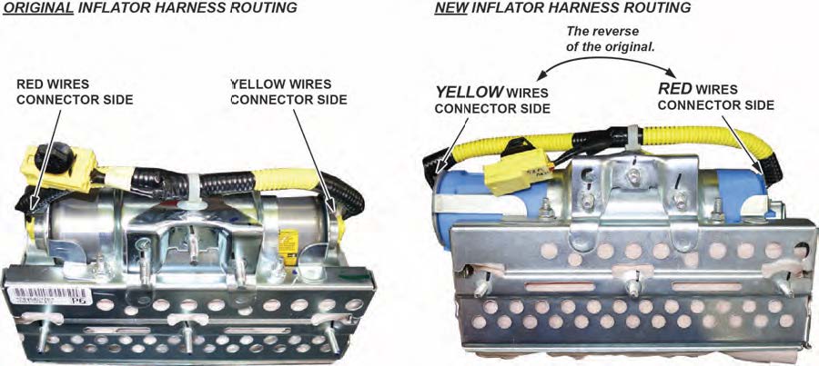
- Install the new inflator harness.
15.1 Make sure the airbag and harness are aligned as shown.
NOTES
- The replacement inflator harnesses have the wire colors in the opposite positions of the original harness. If you connect the harness incorrectly, the harness cannot be removed and you will not be able to reinstall the airbag because the harness will be too short.
- Connect the red wire connector to the short collar side of the inflator with the red dot.
- The red dot may be difficult to see because of the bracket.
15.2 Connect the red wire connector to the connector on the side with the short plastic Align the “T” shape in the inflator harness connector with the T-shaped inflator connector, then press the connector into place.
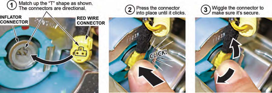
15.3 Connect the yellow wire connector to the connector on the side with the long plastic collar.
15.4 After you hear each connector click, wiggle it to make sure it is secure.
NOTE
If the connector is not properly aligned, it will come out.
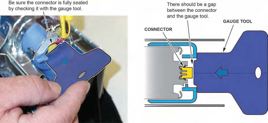
15.5 Make sure the connector is secure and in place by using the gauge tool. (PSPI6 Gauge Tool P/N: 070AJ- TA00A00 or 07AAJ-TA0AA00).
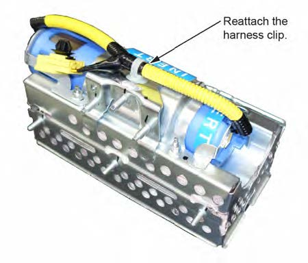
- Connect the harness to the inflator brackets.
- Install the front passenger’s airbag with the new inflator.
17.1 Install the hooks of the front passenger’s airbag into the front passenger’s airbag housing.
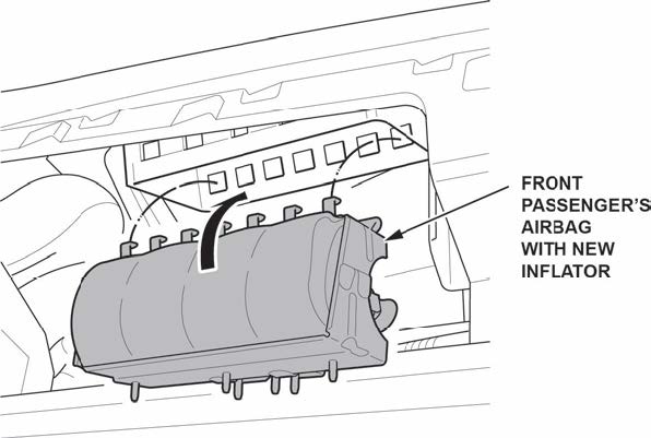
17.2 Insert the hooks of the hook plate into the front passenger’s airbag housing.
17.3 Install the hook plate with the original mounting nuts.
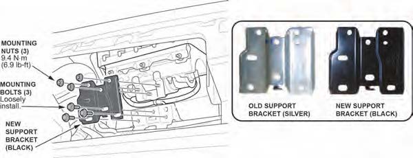
17.4 Install the new support bracket with the new mounting nuts and torque them to 9.4 N·m (6.9 lb-ft), then loosely install the new bolts.
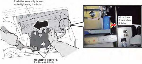
17.5 Push the bracket to the left and hold it while torqueing the mounting bolts to 9.4 N·m (6.9 lb-ft).
NOTE
You must keep the bracket pushed to the left to make sure there is more than 5 mm between the inflator connector and the bracket as shown.
17.6 Connect the dashboard wire harness 4P connector to the front passenger’s airbag 4P connector then install the connector clip.
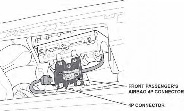
17.7 Install the passenger’s dashboard trim by referring to the service information.
- Reconnect the battery negative cable and enter the anti-theft code for the audio and navigation system (if applicable), then enter the audio presets.
- Set the clock (for vehicles without navigation).
- Turn the ignition to ON and make sure the SRS indicator comes on for about 6 seconds, then goes off.
- Put the original inflator into the box the new one came Make sure there is no other hardware in the box because if the package rattles, it will not be accepted by the courier.
- Follow the shipping instructions outlined in PIB A15-0002 to return the undeployed inflator.
- Give your warranty clerk the RO that includes the replacement inflator serial number and replacement part For the warranty claim to be paid, the replacement inflator part number must be included in the warranty claim.
END
45 Affected Products
Vehicles
| ACURA | TSX | 2009-2013 |
| ACURA | TSX SPORTSWAGON | 2011-2013 |
| ACURA | ZDX | 2010-2013 |
| HONDA | ACCORD | 2009-2012 |
| HONDA | ACCORD CROSSTOUR | 2010-2013 |
| HONDA | CIVIC | 2009-2011 |
| HONDA | CIVIC HYBRID | 2009-2011 |
| HONDA | CR-V | 2009-2011 |
| HONDA | FCX CLARITY | 2013 |
| HONDA | FIT | 2009-2013 |
| HONDA | FIT EV | 2013 |
| HONDA | INSIGHT | 2010-2013 |
| HONDA | PILOT | 2009-2013 |
23 Associated Documents
DIR 3 – VEHICLE INFORMATION BY ZONE (PSPI-6)
RMISC-18V042-9484.pdf 68.026KB
DEFECT INFORMATION REPORT
RMISC-18V042-7890.pdf 58.812KB
Defect Notice 573 Report
RCLRPT-18V042-5771.PDF 249.744KB
Remedy Instructions and TSB – Honda Service Bulletin 18-002 January 10, 2018 Version 1
RCRIT-18V042-6739.pdf 6234.54KB
Manufacturer Notices(to Dealers,etc) – DATE: January 10, 2018 RE: Stop Sale/Safety Recall: 2009-2013 Multi-model Acura Passenger’s Airbag Inflator
RCMN-18V042-9891.pdf 104.954KB
Remedy Instructions and TSB – Service Bulletin 18-002 January 10, 2018 Version 1
RCRIT-18V042-9832.pdf 2938.865KB
News Release
RMISC-18V042-1682.pdf 110.263KB
Manufacturer Notices(to Dealers,etc) – DATE: January 10, 2018 RE: Stop Sale/Safety Recall: 2009-2013 Multi-model Honda Passenger’s Airbag Inflator
Recall Acknowledgement
RCAK-18V042-9191.pdf 311.118KB
573.6(c)(2) Identification of potentially affected vehicles
RMISC-18V042-0837.pdf 39.801KB
Manufacturer Notices(to Dealers,etc) – DATE: February 16, 2018 RE: MAIL UPDATE-Stop Sale/Safety Recall: 2009-2013 Multi-Model Honda Passenger’s Airbag Inflator
ISSUED Owner Notification Letter(Part 577) – HONDA
RCONL-18V042-1246.pdf 294.605KB
ISSUED Owner Notification Letter(Part 577) – ACURA
RCONL-18V042-1945.pdf 275.356KB
Manufacturer Notices(to Dealers,etc) – DATE: February 16, 2018 RE: MAIL UPDATE-Stop Sale/Safety Recall: 2009-2013 Multi-Model Acura Passenger’s Airbag Inflator
ISSUED Renotification Notice
RCRN-18V042-5305.pdf 738.181KB
ISSUED Renotification Notice
RCRN-18V042-7305.pdf 737.853KB
Recall Quarterly Report #1, 2018-1
RCLQRT-18V042-7599.PDF 214.551KB
Recall Quarterly Report #4, 2018-4
RCLQRT-18V042-4998.PDF 211.497KB
Remedy Instructions and TSB
RCRIT-18V042-1916.pdf 5603.819KB
ISSUED Renotification Notice
RCRN-18V042-6202.pdf 119.259KB
ISSUED Renotification Notice
RCRN-18V042-8278.pdf 119.251KB
Remedy Instructions and TSB
RCRIT-18V042-4169.pdf 12782.722KB
Manufacturer Notices(to Dealers,etc) – 12 07 2018 Subject Part Number Changes for Takata Airbag Inflator Safety Recall Bulletins
RCMN-18V042-3040.pdf 140.519KB
1 Associated Investigation
Air Bag Inflator Rupture
NHTSA ID: EA15001
Dated opened: February 24, 2015
The Office of Defects Investigation (ODI) opened PE14-016 in June 2014 based on six inflator rupture incidents involving consumer owned vehicles produced by five vehicle manufacturers. All six vehicles were operated in Florida or Puerto Rico at the time of the rupture and for the majority of their service life, and were equipped with inflators produced by Takata, a tier-one supplier of automotive air bag systems.
During the course of PE14-016, ODI determined that five additional vehicle manufacturers used inflators of a similar design and vintage also supplied by Takata. No evidence of field failures was found in vehicles produced by these five additional manufacturers. Nonetheless, at ODI’s insistence, all 10 vehicle manufacturers initiated a regional recall within approximately two weeks of the opening of the investigation. The regions recalled initially included Florida, Puerto Rico, Hawaii, and the U.S. Virgin Islands, areas with high absolute humidity and climatic conditions believed to be a significant factor in the inflator ruptures. As part of the recall actions, inflators removed from remedied vehicles are to be returned to Takata for testing.
Takata’s initial test results on passenger inflators from remedied vehicles indicated a much higher than anticipated rupture frequency for inflators returned from Florida. Accordingly ODI requested all 10 manufacturers expand the regional recalls for passenger inflators to include other geographic areas where high absolute humidity conditions exist, including the Gulf States and other coastal areas. Takata’s testing of the passenger inflators to date continues to indicate this geographic area as having the highest risk, with no ruptures occurring from inflators returned from outside the expanded recall regions. During PE14-016 four additional passenger inflator field events occurred, all in vehicles from the same expanded geographic region.
Also during PE14-016 four additional driver inflator field events occurred including two in vehicles from regions not known for high absolute humidity, specifically California and North Carolina. Accordingly, ODI requested all five of the affected vehicle manufacturers currently using the subject Takata driver inflators expand to nationwide recalls. Significantly, neither of the affected vehicle manufacturers or Takata provided any explanation to account for these two driver air bag inflator ruptures outside the area of high absolute humidity. Takata testing of returned driver inflators indicates a lower rupture frequency as compared to passenger inflator testing. All test ruptures reported by Takata to date have occurred on inflators returned from high absolute humidity areas.
The investigation now includes all manufacturers and vehicles known to be affected at this time. ODI’s investigation will focus on, among other things, root cause analysis, other potential defect consequences, identification of affected vehicles scope, and adequacy of the remedy.
The five ODI reports cited above can be reviewed online at https://www-odi.nhtsa.dot.gov/owners/SearchNHTSAID under the following identification numbers: 10537899, 10568848, 10585224, 10605877, 10651492
Recalls Documents
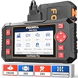
- [Easy to Use—Work Out of the Box] + [FOXWELL 2026 New Version] FOXWELL NT604 Elite scan tool is the 2026 new version from FOXWELL, designed for car owners who want to figure out the cause of issues before fixing car problems by scanning common systems like ABS, SRS, engine, and transmission. The NT604 Elite obd2 scanner diagnostic tool comes with the latest software—no need to waste time downloading software first. Plug the scanner into the OBDII port with OBDII cable to start the diagnosis.
- [Affordable] + [Reliable Car Health Monitor] Will you be confused what happens when the warning light of ABS/SRS/transmission/check engine flashes? Instead of taking your cars to dealership, this FOXWELL scanner will help you do a thorough scanning and detection for your cars and pinpoint the root cause. Note:The device is a diagnostic tool, not a repair tool. To turn off a warning light, you must first physically repair the issue causing it. Only then can the scanner be used to clear the corresponding fault code.
- [5 in 1 Car Diagnostic Scanner] Compared with obd scanners (50-100), NT604 Elite code scanner not only includes their OBDII diagnosis but also serves as ABS/SRS scanner, transmission and check engine code reader. When it’s an odb2 scanner, you can use it to check if your car is ready for annual test through I/M readiness menu. In addition, live data stream, built-in DTC library, data play back and print, all these features are a big plus for it. Note: doesn't support maintenance functions like reset or relearn. For the SRS system, NT604 Elite can read and clear common fault codes not caused by a crash, but crash/collision data cannot be cleared.
- [Fantastic AUTOVIN] + [No extra software fee] Through the AUTOVIN menu, this NT604 Elite car scanner allows you to get your V-IN and vehicle info rapidly, no need to take time to find your V-IN and input one by one. What's more, the NT604 Elite ABS SRS scanner supports 60+ car brands from worldwide (America/Asia/Europe). You don’t need to pay extra software fee. AUTOVIN may not work on some older vehicles or certain vehicle brands. If AUTOVIN fails, please input the vin code manually or go to the Diagnostic Menu to select your vehicle model.
- [Solid protective case KO plastic carrying bag] + [Lifetime update] Almost all same price-level car scanner diagnostic tool only offers plastic bag to hold the scanner.However, NT604 Elite automotive scanner is equipped with solid protective case, preventing your obd2 scanner from damage. Then you don’t need to pay extra money to buy a solid toolbox.
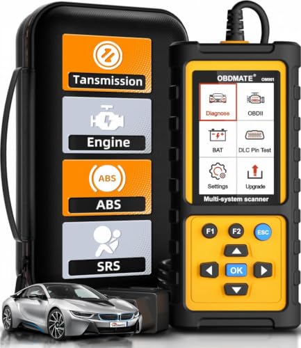
- 【Reset ABS/SRS/Transmission/Engine Lights】 More than an check engine code reader, OBDMATE OM901 obd2 scanner performs comprehensive diagnostics for the 4 most-used systems (ABS/SRS/Engine/Transmission). It quickly clears fault codes, turns off warning lights, read data stream and auto VIN.
- 【3.5" Handheld Scanner with 4 System Diagnose】 3.5" Super large TFT screen equipped displays an intuitive menu and clear readings of various sensors from ABS, SRS, ECM and TCM systems. It arrived with a silicone protective case and hard-shell carrying case, ensuring long-lived durability and drop resistance. The car diagnostic tool is plug-to-play designed, plug it and get diagnosis started without any batteries or updates required.
- 【One-Click I/M Readines&Full OBD2 Functions】 Press F1 to get an intuitive corloured form about whether various emissions-related systems on the vehicle are operating properly. Help you get smog-check ready quickly. OM901 car scanner supports all essential OBD2 functions you need: read & clear codes, view freeze frame, read I/M readiness, retrieve VIN, live data stream (with graphing display), O2 sensor test, onboard monitoring mode, and EVAP leak test.
- 【Battery Voltage Check&DLC Pin Test】 It allows you to monitor battery health by testing current battery voltage. Plus, this obd2 diagnostic tool features DLC 16-PIN test to check current voltage of every pin.
- 【Automotive Scanner Diagnostic Kit】 The package comes with 1 car scanner, 1 USB-type c cable, 1 hard storage bag and 1 user manual(en). Free to update without any hidden fees. 5 languanges available in setting including English, French, Italian, German and Espanish. Valuable and Portable, making it a great tool kit for car owners, DIY enthusiasts, and professional mechanics.
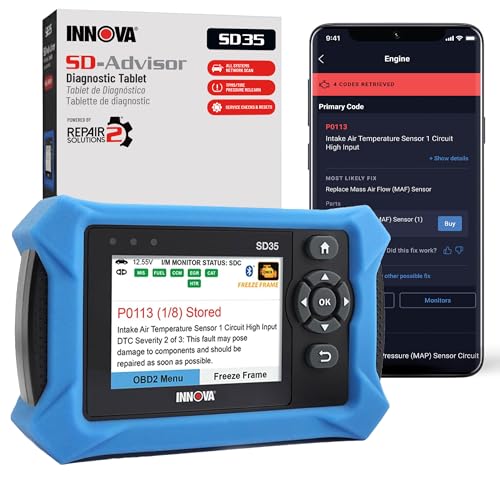
- OBD2 SCANNER FOR ALL SYSTEMS – The INNOVA SD35 is a tablet-based OBD2 scanner designed for advanced diagnostics. Read and clear check engine light, ABS, SRS, and TPMS codes, plus test your car battery and alternator to prevent unexpected failures. Vehicle coverage may vary. Please use Innova’s Coverage Checker to verify compatibility.
- ALL-SYSTEM DIAGNOSTICS & LIVE DATA – Unlike basic code readers, this OBD2 scanner for all vehicles scans engine, transmission, ABS, SRS, and more. Get real-time live data, including RPM, fuel trims, temperature readings, and oxygen sensor performance.
- OBD2 TABLET WITH USER-FRIENDLY INTERFACE – This automotive scan tool features a high-resolution display, making vehicle diagnostics faster and easier.
- ADVANCED TPMS, OIL RESET & SERVICE FUNCTIONS – Perform TPMS sensor checks, oil light reset, and other service resets with ease This professional diagnostic tool provides comprehensive vehicle maintenance capabilities in one device.
- WIDE VEHICLE COVERAGE (1996 & NEWER CARS & TRUCKS) – This OBD2 scanner Bluetooth tablet is compatible with Toyota, Ford, Honda, Chevrolet, Nissan, Dodge, and more. However, feature coverage may vary. Please use Innova's Coverage Checker to verify coverage.
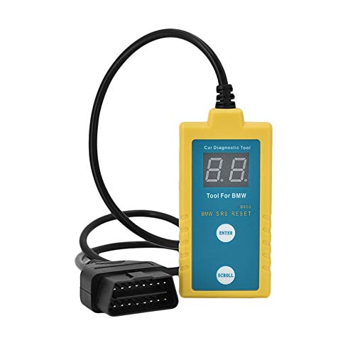
- ✔️【Professional SRS Reset for 1994-2003 BMW】 Designed specifically for classic BMW models (1994-2003). This B800 scanner reads & clears SRS airbag fault codes, turns off the warning light, and saves you a costly dealer visit. Confirmed compatible with: E36, E46 (EXCEPT 2001 330i), E34, E38, E39, Z3, and X5 (E53). NOT compatible with any BMW built before 1994 or after 2003.
- ✔️【Important: Two Different Connection Ports – Read Before Use】 To avoid “not working” issues, please note: For 1994–2000 BMWs (most E36, E34, Z3, early E39), the SRS diagnostic port is a round 20-pin connector under the hood. You MUST use the included 16-pin to 20-pin adapter cable. For 2000–2003 models (late E46, E39, X5), use the standard OBD-II port inside the cabin. Incorrect connection is the #1 reason for “incompatibility” reports.
- ✔️【Read & Clear Fault Codes in Minutes】 Quickly diagnose why your SRS light is on. The scanner accurately reads fault codes from airbag and seatbelt pretensioner systems. With one button press, clear the codes and reset the SRS warning light in seconds. No expensive dealer tools needed.
- ✔️【User-Friendly for DIYers – No Mechanic Required】 Easy operation with an intuitive button layout: ‘Enter’ to confirm, ‘Scroll’ to navigate. The clear LCD screen shows results instantly. Includes a step-by-step manual (revised for clarity) to guide you through the entire reset process.
- ✔️【Reliable Support with 1-Year Warranty】 We stand behind the quality of our B800 scanner. It comes with a 1-Year Hassle-Free Warranty. If you have any questions or need support, please contact us with your Order ID, and our dedicated team will assist you promptly.
- [All System Diagnostics, Professional-Level Scanner] - BLCKTEC 460T is the ultimate OBD2 diagnostic tool for home mechanics and professionals. It supports all 10 OBD2 modes, reads and clears Engine/Transmission/ABS/SRS codes, performs All-System Diagnostics, offers workshop reset tools, and provides real-time live data. It helps you pinpoint issues, assess your car's condition, and prepare for SMOG checks with ease. NOTE: Function availability depends on your vehicle. Before you buy, be sure to use the Compatibility Checker on BLCKTEC website or contact our customer support to verify that the features you need are supported for your vehicle’s specific year, make, and model.
- [12+ Most Popular Reset Functions] - BLCKTEC 460T OBD2 scanner offers 12+ dealer-level service functions, including Oil Maintenance Reset, ABS Bleeding, EPB Reset, SAS(Steering Angle Sensor) Recalibration, DPF(Diesel Particulate Filter) Reset, Throttle Body Relearn, Battery Reset/Initialization, TPMS Relearn, Transmission Reset, Fluid Change Reset, Maintenance Reset and more, enabling you to perform workshop services like a pro. NOTE: Function availability depends on your vehicle. Be sure to use the Compatibility Checker on BLCKTEC website to verify that the features you need are supported for your vehicle.
- [Real-Time OBD2 and OEM Live Data, Freeze Frame Data] - BLCKTEC 460T helps diagnose vehicle issues when warning lights like Check Engine Light or ABS/SRS Light appear. It offers detailed DTC info, ECU Freeze Frame Data, and real-time OBD2 and advanced OEM live data, including Engine, Transmission, ABS, SRS, and more, making it easy to diagnose and resolve vehicle problems. You can view, graph, record, replay, and overlay up to four live data streams in a single graph for better analysis.
- [AutoVIN, AutoReLink, AutoScan, 3X Faster] - Equipped with AutoVIN technology, 460T automatically retrieves the VIN to save you time. Its AutoScan and AutoReLink features scan all of the vehicle's ECUs and detect any fault codes immediately after you plug the scanner into the vehicle's OBD2 port - no button presses required. Additionally, it regathers DTC and I/M readiness information every 30 seconds, simplifying monitor tests. 460T's advanced technology makes it 3X faster than other products.
- [Get RepairSolutions2, the #1 Auto Repair App for Free] - When paired with RepairSolutions2(RS2) App, 460T becomes even more powerful. RS2's Verified Fix Database built by master technicians, provides the parts needed for the repair. Additionally, RS2 gives you access to OEM warranty info, maintenance schedules, TSB, and dealership recall info, making car care easier than ever. RS2 is free with no subscription fees and it stores your car scan reports in the cloud, allowing you to access, share, or print them anytime and anywhere.
This product presentation was made with AAWP plugin.