Acura and Honda hybrid vehicles are equipped with high-voltage (HV) nickel-metal-hybrid (Ni-MH) or lithium-ion (Li-Ion) battery packs, which must be recycled when they have reached the end of their useful life or when the vehicle is dismantled.
This information manual is being provided to support vehicle dismantlers (vehicle salvage/scrap yards) that might not otherwise have access to Acura or Honda service manuals. This manual contains detailed instructions concerning the proper removal and handling of the high-voltage batteries found in these vehicles.
NOTE: This manual is only intended for vehicle dismantlers who disassemble and scrap vehicles at the end of their useful life. Vehicle repair technicians and other personnel who may need information about the removal or exchange of an Acura or Honda hybrid battery should follow the instructions made available through Service Express at www.techinfo.honda.com.
SERVICE INFORMATION
The information contained in this manual is intended for use by qualified technicians. Attempting to perform these procedures without the proper training, tools, and equipment could cause injury to you or others.
Any person who intends to use a procedure or a tool that is not recommended by Acura or Honda must first determine the risks to their personal safety.
When removing and preparing an Acura or Honda hybrid battery pack for recycling, be sure to follow all warnings and precautions provided in this manual and adhere to all federal, state, and local laws relating to the management of these batteries at your facility.
FOR YOUR SAFETY
Because this manual is intended for professionals, we do not provide warnings about many basic safety practices. If you have not received the appropriate safety training or do not feel confident about your knowledge of safe handling of the hybrid batteries, we strongly recommend that you not attempt to do the procedures described in this manual.
Failure to properly follow instructions and precautions can cause you to be seriously hurt or killed. Follow the procedures and precautions in this manual carefully.
IMPORTANT SAFETY PRECAUTIONS
Make sure you have a clear understanding of all basic shop safety practices and that you are wearing appropriate clothing and using appropriate safety equipment. When doing any service task, be especially careful of the following:
Read all of the instructions before you begin, and make sure you have the tools and the skills required to do the tasks safely and completely.
Protect your eyes by using proper safety glasses, goggles, or face shields.
Use other protective gear when necessary, such as insulated gloves or protective goggles.
Protect yourself and others whenever you have the vehicle up in the air. Anytime you raise the vehicle, either with a lift or a jack, make sure that it is always securely supported. Use safety stands if needed.
When removing or installing items marked with , always use insulated tools and wrap the items with insulating tape.
Hybrid Battery Labels. You will find safety and information labels affixed on or near the hybrid battery. Some examples are shown below.
SPECIAL TOOLS
In addition to basic mechanic tools, you will also need the following when removing a high-voltage battery.
Insulated gloves, protective goggles, and protective shoes. Check the gloves for pin holes, tears, or other damage.
The high-voltage cables and their covers are colored bright orange. Warning labels are attached to high-voltage and other related parts. When the system is energized, be careful not to touch these cables and parts without adequate protective gear.
Be sure to shut off the electrical circuits and isolate the high-voltage system and related parts before servicing the system.
Always use insulated tools when servicing, disassembling, or replacing items marked with in each procedure even if the hybrid battery module switch is turned to OFF.
After disconnecting the high-voltage terminals, bus bars, etc., insulate the parts with insulating tape.
Do your best to avoid touching bare wires that could carry high voltage. If you must touch them, first put on insulated gloves and measure the voltage between the module and body ground. If the voltage is above the 12 V battery voltage, insulate the part with insulating tape before performing any operation to prevent shorting the high-voltage battery
When insulating a high-voltage area with insulating tape, be sure to cover it thoroughly.
Check around the battery module for leaks. If you find a leak, do your best to avoid touching it. If you must touch it, first put on insulated gloves and protective goggles.
Keep sparks and flames away from the high-voltage battery since the electrolyte may be flammable.
Seal the removed high-voltage battery in a polypropylene (PP) bag, and keep it in a well-ventilated area away from sparks and flames.
Once you have removed the HV battery from the vehicle, please contact American Honda’s Hybrid Battery Consolidation Center at 1(800)-555-3497 for shipping instructions.
American Honda Hybrid Battery Consolidation Center 14286 Monte Vista Ave. Chino, CA 91701 (800) 555-3497
NOTE: Some newer hybrid models use a lithium-ion battery. These batteries are handled as regulated hazardous material and returns require special handling with certified packaging and documentation.
Remove the rear seat cushion, the seat side bolsters, and the rear seat-back.
Remove the main switch cover (A).
Raise the lever (A) while pushing the tab (B), then remove the service plug (C). NOTE: When removing or installing the service plug, use insulated tools.
Wait 5 minutes to allow the internal capacitors to discharge.
Wrap the service plug base (A) with insulating tape.
Remove the rear inlet duct (A) and the harness clamp (B).
From the cabin side, remove the bolts (A).
From the trunk side, remove the bolts (A).
From the cabin side, disconnect the high voltage cable (A) terminals and remove the harness clamps (B). Then remove the connector bracket (C).
Disconnect the right lower harness connector (A).
Acura and Honda High-Voltage Battery Packs Information Manual for Vehicle Dismantlers - 2003-2016 Honda & Acura 50">
Remove the connector bracket (B).
Disconnect the sensor connector (A).
Remove the component (B).
From the trunk side, remove the plates (A) and the battery insulator (B).
NOTE: Squeeze inward on the ends of the plates to release the lock tabs.
Remove the left battery outlet duct (A) and the right battery outlet duct (B).
From the cabin side, disconnect the right lower harness connector (A) and remove the harness clamps (B).
Disconnect the right side wire harness connector (A).
Remove the upper front bracket (A) and the harness clamps (B).
From the trunk side, disconnect the left lower harness connector (A).
From the cabin side, remove the left upper mounting bracket (A) and the right upper mounting bracket (B).
Remove the six battery mounting bolts (B) from the battery pack (A).
For the six battery mounting bolts (C) that cannot be removed, lift-up the bolts one at time and install an 80 mm long slit plastic tube (D) around the bolts if available.
NOTE:
The slit plastic tubes are included in the Accord PHEV Battery R&R Equipment Loan Kit (07PHEVBATOLKIT).
The plastic tubes keep the mounting bolts up and out of way to allow battery pack A to slide out.
Place fender covers over the rear fenders and the trunk opening to avoid damaged to the vehicle.
If available, attach the battery removal/installation carrier (B) onto the battery pack. Loosely tighten the bolts (C).
Install the carrier adapter mount (D) with the “A” mark (E) side to the right rear battery pack mount. Loosely tighten the bolts (F).
Tighten the five bolts (C and F) to 24.4 N·m (2.49 kgf·m, 18.0 lbf·ft).
If available, install the inside handle (A) to the battery removal/installation carrier (B) and install the pin (C).
If available, set the battery removal/installation table (D) in the trunk area as shown (table legs extended).
With the help of an assistant on the inside of the vehicle, carefully lift and transfer the battery pack onto the battery removal/installation table (B).
If attached, remove the inside handle (C) from the battery pack removal/installation carrier (D).
With the help of an assistant at the rear of the vehicle, carefully lift-up the battery pack and remove it from the trunk area. If available, set the battery pack on the work surface provide with the Accord PHEV Battery R&R Equipment Loan Kit (07PHEVBATOLKIT).
From the cabin side, remove the cable bracket (A).
Disconnect the sensor connector (A).
Remove the sensor (B).
Disconnect the left side wire harness connector (A).
Remove the left side cover (B).
Remove the left air inlet trim (A).
Remove the left battery inlet duct (A).
From the trunk side, remove the lower mounting brackets (A).
From the cabin side, remove the center frame bolts (A) and the harness clamp (B).
From the trunk side, remove the rear cross member bolts (A).
Place fender covers over the rear fenders and the trunk opening to avoid damaged to the vehicle.
If available, attach the battery removal/installation carrier (A) onto the battery pack. Loosely tighten the bolts (C).
If available, install the carrier adapter mount (D) with the “B” mark (E) side to right rear battery pack mount. Loosely tighten the bolts (F).
Tighten the five bolts (C and F) to 24.4 N·m (2.49 kgf·m, 18.0 lbf·ft).
If available, install the inside handle (A) to the battery removal/installation carrier (B) and install the pin (C).
If available, set the battery removal/installation table (D) in the trunk area as shown (table legs folded).
With the help of an assistant on the inside of the vehicle, carefully lift and transfer the battery pack onto the battery removal/installation table (A).
Remove the inside handle (C) from the battery pack removal/installation carrier (D).
With the help of an assistant at the rear of the vehicle, carefully lift-up the battery pack and remove it from the trunk area. If available, set the battery pack on the work surface provide with the Accord PHEV Battery R&R Equipment Loan Kit (07PHEVBATOLKIT).
If needed, flip the battery pack up-side-down, and remove the center frame (A).
END
.
2003–05 Civic Hybrid
Disconnect the negative cable to the 12V battery.
Remove the rear seat cushion and the rear seat-back.
Remove the battery module switch lid (A), then remove the locking cover (B).
Turn the battery module switch to OFF and wait 5 minutes. 5. Remove the bolts (A) and the clip (B)
Remove the bolts (A) and the clip (B)
Disconnect the connectors (A), the capacitor ground (B), the clips (C), and the high voltage cables, and wrap the cables with insulating tape.
Remove the bolts (F), the stopper (G), and the HV battery pack (H).
END
.
2006–11 Civic Hybrid
Disconnect the negative cable to the 12V battery.
Remove the rear seat-back and the rear seat cushion.
Remove the battery module switch lid.
Turn the battery module switch (A) to OFF, then check that the bolt (B) is showing.
Wait 5 minutes to allow the internal capacitors to discharge.
Remove the bolts (A) and (B), then remove the lid (C).
Remove the high-voltage cables (A), then wrap them with insulating tape (B).
Disconnect the connectors (C) and (D).
Remove the bolts (E), then remove the HV battery pack (F).
END
.
2012–15 Civic Hybrid
Disconnect the negative cable of the 12V battery.
Remove the rear seat cushion, the seat side bolsters, and the rear seat-back.
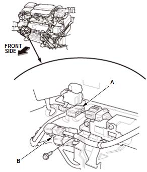
Remove the main switch cover (A).
Turn the battery module switch (B) to OFF, then check that the bolt (C) is showing.
Wait 5 minutes to allow the internal capacitors to discharge.
Remove the cover.
Remove the air inlet duct.
Disconnect the connectors (A).
Remove the cables (B).
Remove the battery pack.
END
.
2011–12 CR-Z
Disconnect the negative cable to the 12V battery.
Remove all of the rear trim components.
Remove the spare tire.
Remove the cargo lid and floor box.
Loosen the bolt (A) and remove the bolt (B). Remove lid (C).
Turn the battery module switch (A) to OFF, then check that the bolt (B) is showing.
Wait at least 5 minutes to allow the capacitors to discharge.
Pull up the duct cover (A) by hand to detach the clips and the hooks (B), then remove the duct cover.
Remove the bolts and the cover guard (A).
Remove the air ducts (A).
Remove the bolts (A, B) and the clips (C), then remove the cover (D).
Remove the bolts (A) and the lid (B).
Disconnect the four power cables (A) from the phase motor current sensor, then wrap the end of the 12V power cable (B) with insulating tape.
Remove the cable clamp (C).
Disconnect the connector (A).
Remove the bolts (B, C), then remove the HV battery pack (D).
END
.
HV BATTERY REMOVAL INSTRUCTIONS
2013–16 CR-Z
Disconnect the negative cable to the 12V battery.
Remove all of the rear trim components as needed.
Remove the spare tire.
Remove the cargo lid and floor box.
Remove the battery module switch lid (A) from the cover.
Remove the bolt (A) from the battery module switch.
Turn the battery module switch OFF by sliding the extension of the switch in the direction of the arrow as shown.
Remove the bolt (A).
Wait at least 5 minutes to allow the capacitors to discharge.
Pull up the duct cover (A) by hand to detach the clips and the hooks (B), then remove the duct cover.
Remove the bolts and the cover guard (A).
Remove the bolts (A, B) and the clips (C), then remove the cover (D).
Remove the lid (A).
Remove the motor power cable terminals (W, V, U).
Remove the 12V power cable (A) and wrap the end of the cable terminal with insulating tape.
Remove the cable clamp (B).
Disconnect the harness connector (A) and remove the ground cable mounting bolt (B).
Remove the bolts (A), then remove the HV battery pack (B).

 and Honda


 Acura
Acura


 Loading...
