| “This site contains affiliate links for which OEMDTC may be compensated” |
B98-037
February 28, 2000
Applies To: 1999–00 3.2TL – ALL
ABS and TCS Indicators Come On With DTCs 28, 81 (TCS) and/or 52, 53, 54, 81 (ABS)
(Supersedes 98-037, ABS and TCS Indicators Are On and TCS DTC 28 Is Set, dated March 15, 1999)
SYMPTOM
The ABS and TCS indicators are on, and one or more of these DTCs are set:
- TCS DTC 28 (TCS Relay)
- TCS DTC 81 (Continuous TCS Operation)
- ABS DTC 52 (Motor Stuck OFF)
- ABS DTC 53 (Motor Stuck ON)
- ABS DTC 54 (ABS Fail-safe Relay)
- ABS DTC 81 (Central Processing Unit [CPU] Diagnosis, and ROM/RAM Diagnosis)
PROBABLE CAUSE
Water in the modulator unit connector.
CORRECTIVE ACTION
Remove any water from the connector, and apply lithium dielectric grease to the connector face.
REQUIRED MATERIALS
WARRANTY CLAIM INFORMATION
In warranty: The normal warranty applies.
| OP# | Description | FRT | Template ID |
| 423501 | Retrieve DTCs | 0.3 | 98-037A |
| 413025 | Repair modulator unit connector | 0.2 |
Failed Part: P/N 57110-S0K-003
Defect Code: 066
Contention Code: D99
Skill Level: Repair Technician
Out of warranty: Any repair performed after warranty expiration may be eligible for goodwill consideration by the District Parts and Service Manager or your Zone Office. You must request consideration, and get a decision, before starting work.
REPAIR PROCEDURE
- Connect a PGM Tester with S/N 000 or later software, and look at the display (see page 19-38 of the 1999-00 3.2TL Service Manual).
- If the PGM Tester shows DTCs other than those listed under SYMPTOM, refer to the appropriate troubleshooting procedure in the service manual.
- If the PGM Tester shows any of the DTCs listed under SYMPTOM, go to step 2.
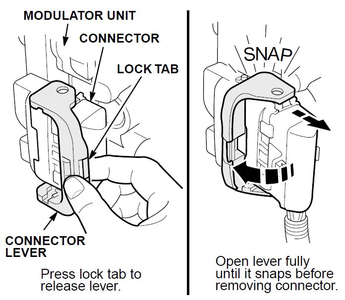
- Unplug the connector from the modulator unit by pressing the lock tab on the connector lever and turning the lever outward until it snaps into place.
- Check the connector for water contamination.
- If it is dry, follow the appropriate troubleshooting procedure on page 19-78 of the service manual.
- If it is wet, go to step 4.
- Use compressed air to dry the connector.
- Apply a light coat of lithium dielectric grease to the connector face. Do not apply too much grease; it will push out the rubber seals in the back of the connector.
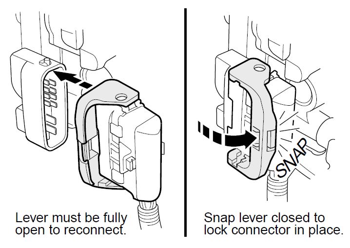
- Plug the connector into the modulator unit by sliding the connector onto the unit and pushing the lever all the way back until it snaps closed.
- Use the PGM Tester to clear any stored DTCs (see page 19-39 of the service manual).
- Start the engine, and check that the ABS and TCS indicators go off.
 Loading...


