| “This site contains affiliate links for which OEMDTC may be compensated” |
A99-065
December 11, 2001
Applies To: 1999–2001 Odyssey – ALL
Inaccurate Odyssey Fuel Gauge
(Supersedes 99-065, 1999 Odyssey: Inaccurate Fuel Gauge, dated August 17, 1999)
SYMPTOM
The fuel gauge needle doesn’t point to “F” after you fill the fuel tank, and/or the fuel gauge reading is not accurate when the tank is between 1/2 and full.
PROBABLE CAUSE
Sulfur deposits from the fuel affect the resistance of the fuel gauge sending unit.
CORRECTIVE ACTION
Replace the fuel gauge sending unit.
PARTS INFORMATION
| Description | Part Number | |
| Fuel Gauge Sending Unit: P/N | 17630-S0X-A03 | H/C 6786289 |
| Base Gasket: P/N | 17574-S1A-E01 | H/C 5928122 |
| Fuel Line Retainer (return): P/N | 17711-S0X-931 | H/C 5928312 |
| Fuel Line Retainer (feed): P/N | 17711-S0X-003 | H/C 5928296 |
| Sealing Washer: P/N | 16705-PD1-003 | H/C 1855675 |
| Sealing Washer: P/N | 90428-PD6-003 | H/C 2128429 |
REQUIRED SPECIAL TOOLS
| Description | Tool Number |
| Fuel Sender Wrench: | 07XAA-001010A |
WARRANTY CLAIM INFORMATION
In warranty: The normal warranty applies.
| Operation Number: | 310120 |
| Flat Rate Time: | 1.0 hour |
| Failed Part: | P/N 17630-S0X-A02 H/C 6183305 |
| Defect Code: | 039 |
| Contention Code: | B99 |
| Template ID: | 99-065A |
| Skill Level: | Repair Technician |
Out of warranty: Any repair performed after warranty expiration may be eligible for goodwill consideration by the District Service Manager or your Zone Office. You must request consideration, and get a decision, before starting work.
REPAIR PROCEDURE
- Remove the second row seats.
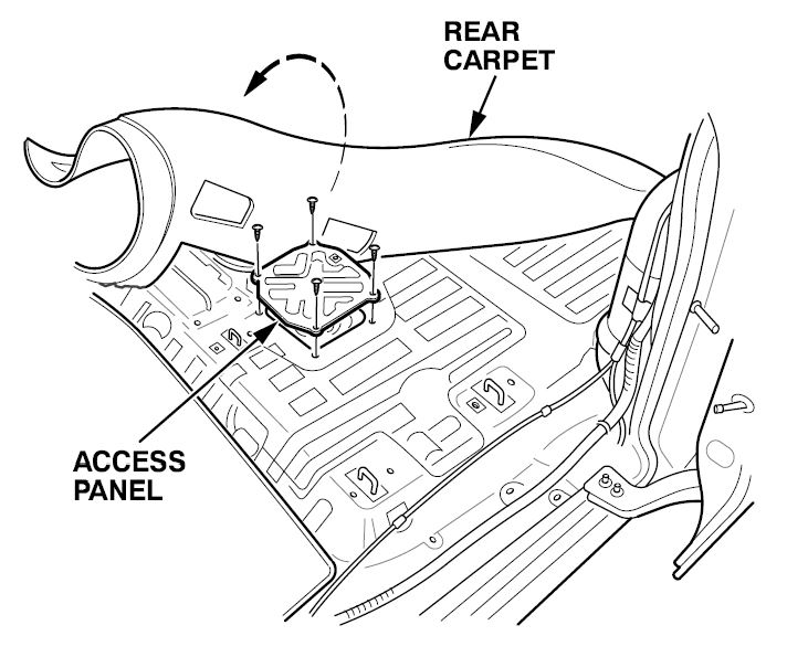
- Pull back enough of the rear carpet to expose the access panel on the floor.
- Remove the access panel.
- Make sure the ignition switch is off, then disconnect the 5P connector from the top of the fuel pump assembly.
- Remove the fuel fill cap.
- Relieve the fuel pressure (see page 11-208 of the 1999–02 Odyssey Service Manual).
NOTE: Whenever you relieve fuel pressure, replace the two sealing washers for the fuel pulsation damper.
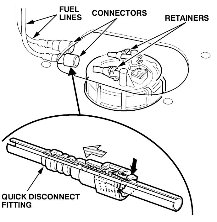
- Disconnect the two fuel lines (quick-disconnect fittings) from the fuel pump assembly: Hold the connector side of the fitting, squeeze the tabs on the retainer, and pull the connector off the fuel line.
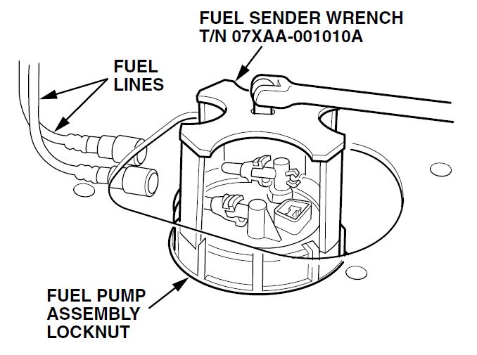
- Remove the fuel pump assembly locknut with the special tool, then lift the fuel pump assembly out of the fuel tank.
- Discard the base gasket between the fuel pump assembly and the fuel tank.
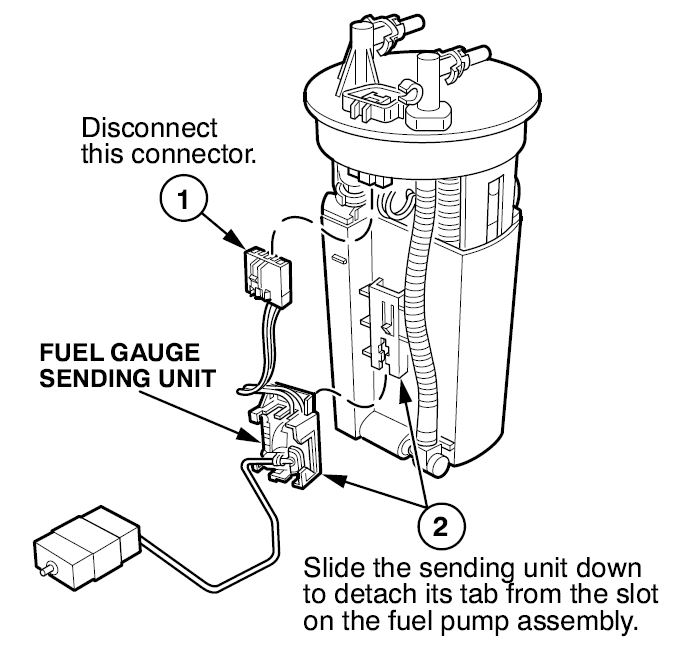
- Remove the fuel gauge sending unit from the fuel pump assembly.
- Install the new fuel gauge sending unit.
- Place a new base gasket around the opening in the tank, then carefully insert the fuel pump assembly into the opening.
- Install the locknut over the fuel pump assembly, then use the special tool to torque the locknut to 93 N.m (69 ft-lb).
- Remove and discard the two fuel line retainers from the top of the fuel pump assembly.
- Insert new fuel line retainers into the connector side of the quick disconnect fittings, then connect the fuel lines to the fuel pump assembly (see pages 11-218 and 11-219 of the service manual).
- Connect the 5P connector to the fuel pump assembly.
- Turn the ignition switch to ON (II), and make sure there are no leaks at the fuel lines and the base gasket.
- Turn the ignition switch off, then install the access panel, the carpet, and the seats.
- Install the fuel fill cap, and tighten it until it clicks at least three times.
 Loading...


