
A23-079
August 18, 2023
Version 1
Safety Recall: 2023 Accord FHEV e-CVT Replacement
AFFECTED VEHICLES
| Year | Model | Trim | VIN Range |
| 2023 | Accord | Hybrid | Check the VIN status for eligibility |
BACKGROUND
A resolver is a rotation angle sensor for controlling an electric motor. The generator motor resolver covers in affected vehicles may have been damaged during the manufacturing process. Over time, this damage may cause the cover to separate from the resolver, potentially contacting and cutting the resolver wire harness and leading to resolver malfunction. This malfunction may cause illumination of the MIL, the engine to transition to EV mode with range limited by battery capacity, and/or prevent the vehicle from restarting.
CUSTOMER NOTIFICATION
Owners of affected vehicles will be sent a notification of this safety recall.
Do an iN VIN status inquiry to verify eligibility.
Some vehicles affected by this campaign may be in your new or used vehicle inventory.
Failure to repair a vehicle subject to a recall or campaign may subject your dealership to claims or lawsuits from the customer or anyone else harmed as a result of such. To see if a vehicle in inventory is affected by this safety recall, do a VIN status inquiry before selling it.
CORRECTIVE ACTION
Replace the e-CVT transmission.
PARTS INFORMATION
| Part Name | Part Number | Quantity |
| ATR Kit | 20041-6MR-A02RM | 1 |
| Exhaust Pipe Gasket | 18302-SP0-003 | 1 |
| Exhaust Pipe Gasket | 18303-T2B-A01 | 1 |
| Drain Gasket (TOYO) | 19012-PD2-004 | 1 |
| Set-Ring (30X2.2) (Set Ring) | 44319-S0X-A01 | 1 |
| Set-Ring (30X2.2) (Set Ring) | 44319-SD4-010 | 1 |
| Lower Torque Rod | 50890-3D4-A51 | 1 |
| Bolt-Washer (14X45) | 90163-TGH-A01 | 2 |
| Bolt-Washer (14X85) | 90130-T20-A00 | 1 |
| Flange Bolt (14X33) | 90164-T20-A00 | 5 |
| Flange Bolt (12X50) | 90167-TBA-A00 | 2 |
| Flange Bolt (14X50) | 90168-SMG-E01 | 3 |
| Flange Bolt (14×105) | 90175-3A0-A00 | 1 |
| Flange Bolt (14×105) | 90175-TRW-A00 | 1 |
| Bolt-Washer (14X85) | 90179-T20-A01 | 6 |
| Flange Bolt (14X50) | 90181-TLA-A00 | 2 |
| Flange Bolt (14X35) | 90181-TBA-A00 | 2 |
| Self-Lock Nut (10mm) | 90212-SA5-003 | 8 |
| Self-Lock Nut (12mm) (Clinch) (Sato Rashi) | 90215-SB0-003 | 6 |
| Spindle Nut | 90305-S3V-A11 | 2 |
| Self-Lock Nut (12mm) (Clinch) | 90370-SJA-000 | 6 |
| Flange Nut (12mm) | 90371-TBA-A00 | 1 |
| Drain Plug Washer (18mm) | 90471-PX4-000 | 1 |
| Drain Plug Washer (20mm) | 94109-20000 | 1 |
| Split Pin (3.0X22) | 94201-30220 | 2 |
REQUIRED MATERIALS
| Part Name | Part Number | Quantity |
| Super High Temp Urea Grease | 08798-9002 | 1 (1 container can repair up to 20 vehicles) |
| HEVF Type-1 | 08200-9022 | 5 |
| Honda Long Life Antifreeze/Coolant Type 2 | OL999-9011 | 1 |
TOOL INFORMATION
| Tool Part Number | Description |
| 7MAC-SL00102/ 07MAC-SL00202 | Ball Joint Remover |
| 07AAF-SDAA100/07AAE-SJAA100 | Protector |
| 07AAK-SNAA120 | Universal Lift Eyelet |
| AAR-T1256 | Engine Hanger |
| VSB02C000016 | Subframe Holder |
| 070AG-SJAA10S | Subframe Alignment Pin |
REPAIR PROCEDURE
In PDF Bellow…
NFG & HFF – Loss of Drive Power – 2023 Honda CR-V Hybrid & Accord Hybrid
Safety Recall: 2023 Honda Accord FHEV e-CVT Replacement
Remedy Instructions and TSB
RCRIT-23V588-7048.PDF 2501.299KB
Latest Recalls Documents
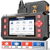
- [Easy to Use—Work Out of the Box] + [FOXWELL 2026 New Version] FOXWELL NT604 Elite scan tool is the 2026 new version from FOXWELL, designed for car owners who want to figure out the cause of issues before fixing car problems by scanning common systems like ABS, SRS, engine, and transmission. The NT604 Elite obd2 scanner diagnostic tool comes with the latest software—no need to waste time downloading software first. Plug the scanner into the OBDII port with OBDII cable to start the diagnosis.
- [Affordable] + [Reliable Car Health Monitor] Will you be confused what happens when the warning light of ABS/SRS/transmission/check engine flashes? Instead of taking your cars to dealership, this FOXWELL scanner will help you do a thorough scanning and detection for your cars and pinpoint the root cause. Note:The device is a diagnostic tool, not a repair tool. To turn off a warning light, you must first physically repair the issue causing it. Only then can the scanner be used to clear the corresponding fault code.
- [5 in 1 Car Diagnostic Scanner] Compared with obd scanners (50-100), NT604 Elite code scanner not only includes their OBDII diagnosis but also serves as ABS/SRS scanner, transmission and check engine code reader. When it’s an odb2 scanner, you can use it to check if your car is ready for annual test through I/M readiness menu. In addition, live data stream, built-in DTC library, data play back and print, all these features are a big plus for it. Note: doesn't support maintenance functions like reset or relearn. For the SRS system, NT604 Elite can read and clear common fault codes not caused by a crash, but crash/collision data cannot be cleared.
- [Fantastic AUTOVIN] + [No extra software fee] Through the AUTOVIN menu, this NT604 Elite car scanner allows you to get your V-IN and vehicle info rapidly, no need to take time to find your V-IN and input one by one. What's more, the NT604 Elite ABS SRS scanner supports 60+ car brands from worldwide (America/Asia/Europe). You don’t need to pay extra software fee. AUTOVIN may not work on some older vehicles or certain vehicle brands. If AUTOVIN fails, please input the vin code manually or go to the Diagnostic Menu to select your vehicle model.
- [Solid protective case KO plastic carrying bag] + [Lifetime update] Almost all same price-level car scanner diagnostic tool only offers plastic bag to hold the scanner.However, NT604 Elite automotive scanner is equipped with solid protective case, preventing your obd2 scanner from damage. Then you don’t need to pay extra money to buy a solid toolbox.
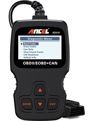
- CEL Doctor: The ANCEL AD310 is one of the best-selling OBD II scanners on the market and is recommended by Scotty Kilmer, a YouTuber and auto mechanic. It can easily determine the cause of the check engine light coming on. After repairing the vehicle's problems, it can quickly read and clear diagnostic trouble codes of emission system, read live data & hard memory data, view freeze frame, I/M monitor readiness and collect vehicle information
- Sturdy and Compact: Equipped with a 2.5 foot cable made of very thick, flexible insulation. It is important to have a sturdy scanner as it can easily fall to the ground when working in a car. The AD310 OBD2 scanner is a well-constructed mechanic tool with a sleek design. It weighs 12 ounces and measures 8.9 x 6.9 x 1.4 inches. Thanks to its compact design and light weight, transporting the device is not a problem. The buttons are clearly labelled and the screen is large and displays results clearly
- Accurate Fast and Easy to Use: The AD310 scanner can help you or your mechanic understand if your car is in good condition, provides exceptionally accurate and fast results, reads and clears engine trouble emission codes in seconds after you fixed the problem. This device will let you know immediately and fix the problem right away without any car knowledge. No need for batteries or a charger, get power directly from the OBDII Data Link Connector in your vehicle
- OBDII Protocols and Car Compatibility: Many cheap scan tools do not really support all OBD2 protocols. AD310 scanner as it can support all OBDII protocols such as KWP2000, J1850 VPW, ISO9141, J1850 PWM and CAN. This device also has extensive vehicle compatibility with 1996 US-based, 2000 EU-based and Asian cars, light trucks, SUVs, as well as newer OBD2 and CAN vehicles both domestic and foreign. Pls confirm with our customer service whether it is compatible with your vehicle before purchasing
- Home Necessity and Worthy to Own: This is an excellent code reader to travel or home with as it weighs less and it is compact in design. You can easily slide it in your backpack as you head to the garage, or put it on the dashboard, this will be a great fit for you. The AD310 is not only portable, but also accurate and fast in performance. Moreover, it covers various car brands and is suitable for people who just need a code reader to check their car
- [All System Diagnostics, Professional-Level Scanner] - BLCKTEC 460T is the ultimate OBD2 diagnostic tool for home mechanics and professionals. It supports all 10 OBD2 modes, reads and clears Engine/Transmission/ABS/SRS codes, performs All-System Diagnostics, offers workshop reset tools, and provides real-time live data. It helps you pinpoint issues, assess your car's condition, and prepare for SMOG checks with ease. NOTE: Function availability depends on your vehicle. Before you buy, be sure to use the Compatibility Checker on BLCKTEC website or contact our customer support to verify that the features you need are supported for your vehicle’s specific year, make, and model.
- [12+ Most Popular Reset Functions] - BLCKTEC 460T OBD2 scanner offers 12+ dealer-level service functions, including Oil Maintenance Reset, ABS Bleeding, EPB Reset, SAS(Steering Angle Sensor) Recalibration, DPF(Diesel Particulate Filter) Reset, Throttle Body Relearn, Battery Reset/Initialization, TPMS Relearn, Transmission Reset, Fluid Change Reset, Maintenance Reset and more, enabling you to perform workshop services like a pro. NOTE: Function availability depends on your vehicle. Be sure to use the Compatibility Checker on BLCKTEC website to verify that the features you need are supported for your vehicle.
- [Real-Time OBD2 and OEM Live Data, Freeze Frame Data] - BLCKTEC 460T helps diagnose vehicle issues when warning lights like Check Engine Light or ABS/SRS Light appear. It offers detailed DTC info, ECU Freeze Frame Data, and real-time OBD2 and advanced OEM live data, including Engine, Transmission, ABS, SRS, and more, making it easy to diagnose and resolve vehicle problems. You can view, graph, record, replay, and overlay up to four live data streams in a single graph for better analysis.
- [AutoVIN, AutoReLink, AutoScan, 3X Faster] - Equipped with AutoVIN technology, 460T automatically retrieves the VIN to save you time. Its AutoScan and AutoReLink features scan all of the vehicle's ECUs and detect any fault codes immediately after you plug the scanner into the vehicle's OBD2 port - no button presses required. Additionally, it regathers DTC and I/M readiness information every 30 seconds, simplifying monitor tests. 460T's advanced technology makes it 3X faster than other products.
- [Get RepairSolutions2, the #1 Auto Repair App for Free] - When paired with RepairSolutions2(RS2) App, 460T becomes even more powerful. RS2's Verified Fix Database built by master technicians, provides the parts needed for the repair. Additionally, RS2 gives you access to OEM warranty info, maintenance schedules, TSB, and dealership recall info, making car care easier than ever. RS2 is free with no subscription fees and it stores your car scan reports in the cloud, allowing you to access, share, or print them anytime and anywhere.
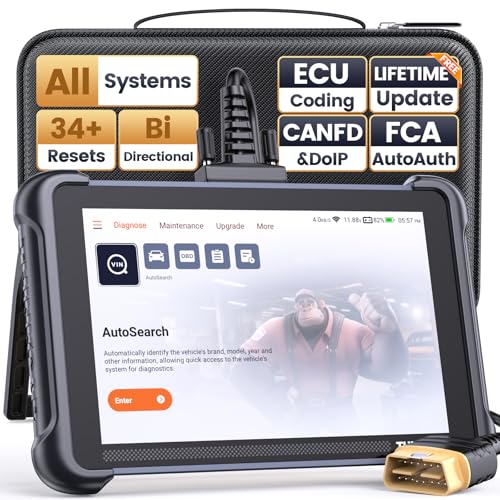
- 【Warm Tips】Dear friend, we've built this product to last, but in the unlikely event you encounter any technical hiccups, functions not support, received a used product, or just a simple question, please directly c0ntact us via Amazon Message and support @ mythinkcar. com, we're here to help and get it sorted in no time. Not sure if this product is compatible with your vehicle? Just e.mail your VIN at support @ mythinkcar. com for technical support. Note: FCA AutoAuth is a third-party service, additional cost may require.
- 【Professional Car Diagnostic Tool】Tired of renew fees? Thinkscan 689 scanner provides dealer-level advanced functions without annual fees for auto mechanics and repair shops. 34+ Services, 3000+ Active Test, ECU Coding, 140+ Brands Coverage, FCA AutoAuth, CANFD&DOIP Protocol, Component Matching, Power Balance, V.A.G Guided, Compatible with Google Chrome integration, etc. With strong hardware backing, 64G Memory, Android 10, 4-core processors, and 4150mAh battery. Thinkscan 689 brings you the best as your daily business helper and never lets you drop the ball!
- 【34+ Reset Service, Adaptation, Relearn, Calibration, Initialization, Matching】Made for workshops, Thinkscan 689 scanner provides 34+ services for worldwide vehicles: such as Gear/SAS/EPB/TPMS/D.P.F/BMS/ETS/Oil/Brake/AFS/GEARB0X/SUNROOF/SUS Reset, ABS Bleed, Injector coding, etc. Warm tips: Compatibility varies by car model, please reach out to us directly to make sure it works well on your cars.
- 【Real Active Test】Thinkscan 689 scan tool features over 3000+ full bi-directional control ability, to send commands to vehicle’s systems/components, to verify system input/output without using the vehicle's controls, e.g. turn on the radiator fan, modulate the throttle, open/close windows, operate mirrors, Injector Buz Test, turn on interior&exterior lights, sound horn, test door lock actuators, turn on/off front/rear side ACM Solenoid, Vehicle level position calibration, Wheel Speed Sensor Supply.
- 【Comprehensive Solutions with Advanced Features】Take your vehicle customization to the next level with the Thinkscan 689's advanced ECU coding capabilities. This scan tool provides power balance, PMI, unlock hidden features and enhance performance by activating dormant functions, customizing OE settings, matching replaced components, and reprogramming adaptive data to elevate your driving experience. Note: Compatibility varies by car models, please check before order.


- 2026 Advanced ECU Coding Scan Tool: Maximize the capabilities of your vehicles with the ArtiDiag Pro. This scan tool, seamlessly compatible with renowned models such as VW, A-U-D-I, SKODA, SEAT, BENZ, and more, empowers you to uncover hidden features, deactivate annoying functions, and code retrofitted components for peak performance. Ensure a backup before coding and steer clear of problems on low battery levels.
- Efficient Diagnostics with Bidirectional Control: Say goodbye to uncertainty, streamline diagnostics, and reclaim valuable time with ArtiDiag Pro scan tool. This bidirectional scan tool exceeds expectations, enabling targeted tests on individual actuators to swiftly identify and resolve issues. Covering lights, door locks, fuel and coolant systems, windows, wipers, EVAP, and more in vehicle components.
- 35+ Services Resolve 90% of Repair Challenges: Unleash maximum productivity with the ArtiDiag Pro, a scan tool that tackles 90% of maintenance issues through its 35 special functions. Effortlessly clear oil maintenance indicators with oil reset. Engage the EPB Reset for brake system management and establish precise alignment with the Steering Angle Reset to define the straight-line reference position for your vehicle.
- FCA Autoauth : This diagnostic tool supports Autoauth for FCA SGW/Renault, Chrysler, Jeep, Dodge, Fiat etc. 2017 and later. NOTE: Due to Product Upgrade, there is no Chrysler 12+8 adapter, the BMW-20 Adapter in the package any more. We are sincerely sorry for the inconvenience. NOTE: Please confirm compatibility before purchase.(Topdon Website>Support>Vehicle Coverage)
- Professional Customer Support: At TOPDON, your satisfaction is our unwavering commitment. Experience hassle-free support and a lifetime of expert assistance. Should you encounter any challenges, reach out to us at 833-629-4832. For returns, please damage the packaging to prevent Amazon from reselling it. Please be advised that after two years, a subscription fee of 249 Bucks will apply.
SEOCONTENT-START
Service Bulletin 23-079 August 18, 2023 Version 1 Safety Recall: 2023 Accord FHEV e-CVT Replacement AFFECTED VEHICLES Year Model Trim VIN Range 2023 Accord Hybrid Check the VIN status for eligibility BACKGROUND A resolver is a rotation angle sensor for controlling an electric motor. The generator motor resolver covers in affected vehicles may have been damaged during the manufacturing process. Over time, this damage may cause the cover to separate from the resolver, potentially contacting and cutting the resolver wire harness and leading to resolver malfunction. This malfunction may cause illumination of the MIL, the engine to transition to EV mode with range limited by battery capacity, and/or prevent the vehicle from restarting. CUSTOMER NOTIFICATION Owners of affected vehicles will be sent a notification of this safety recall. Do an iN VIN status inquiry to verify eligibility. Some vehicles affected by this campaign may be in your new or used vehicle inventory. Failure to repair a vehicle subject to a recall or campaign may subject your dealership to claims or lawsuits from the customer or anyone else harmed as a result of such. To see if a vehicle in inventory is affected by this safety recall, do a VIN status inquiry before selling it. CORRECTIVE ACTION Replace the e-CVT transmission. CUSTOMER INFORMATION:The information in this bulletin is intended for use only by skilled technicians who have the proper tools, equipment, and training to correctly and safely maintain your vehicle. These procedures should not be attempted by “do-it-yourselfers,” and you should not assume this bulletin applies to your vehicle, or that your vehicle has the condition described. To determine whether this information applies, contact an authorized Honda automobile dealer. © 2023 American Honda Motor Co., Inc. — All Rights Reserved Page 1 of 38 PARTS INFORMATION Part Name Part Number Quantity ATR Kit 20041-6MR-A02RM 1 Exhaust Pipe Gasket 18302-SP0-003 1 Exhaust Pipe Gasket 18303-T2B-A01 1 Drain Gasket (TOYO) 19012-PD2-004 1 Set-Ring (30X2.2) (Set Ring) 44319-S0X-A01 1 Set-Ring (30X2.2) (Set Ring) 44319-SD4-010 1 Lower Torque Rod 50890-3D4-A51 1 Bolt-Washer (14X45) 90163-TGH-A01 2 Bolt-Washer (14X85) 90130-T20-A00 1 Flange Bolt (14X33) 90164-T20-A00 5 Flange Bolt (12X50) 90167-TBA-A00 2 Flange Bolt (14X50) 90168-SMG-E01 3 Flange Bolt (14×105) 90175-3A0-A00 1 Flange Bolt (14×105) 90175-TRW-A00 1 Bolt-Washer (14X85) 90179-T20-A01 6 Flange Bolt (14X50) 90181-TLA-A00 2 Flange Bolt (14X35) 90181-TBA-A00 2 Self-Lock Nut (10mm) 90212-SA5-003 8 Self-Lock Nut (12mm) (Clinch) (Sato Rashi) 90215-SB0-003 6 Spindle Nut 90305-S3V-A11 2 Self-Lock Nut (12mm) (Clinch) 90370-SJA-000 6 Flange Nut (12mm) 90371-TBA-A00 1 Drain Plug Washer (18mm) 90471-PX4-000 1 Drain Plug Washer (20mm) 94109-20000 1 Split Pin (3.0X22) 94201-30220 2 Page 2 of 38 1. To order a replacement transmission, fill out the AT/CVT order form under Reman Parts/Special Orders section on the iN. NOTE: • If you have not contacted Tech Line, then use the last 7 digits of the VIN for the Tech Line Reference Number. • If the 11th character of the VIN has a letter instead of a number, replace it with a zero. • Select Tech Line Agent Name—Tech Line. Page 3 of 38 2. Fill out the AT/CVT Order Form under Reman Parts/Special Orders section on the iN. NOTE: Once the CVT order has been received, your order will be reviewed by RPO. Additional requests and images may be required by RPO before release of the CVT. REQUIRED MATERIALS Part Name Part Number Quantity Super High Temp Urea Grease 08798-9002 1 (1 container can repair up to 20 vehicles) HEVF Type-1 08200-9022 5 Honda Long Life Antifreeze/Coolant Type 2 OL999-9011 1 Page 4 of 38 TOOLS INFORMATION Tool Part Number Description 7MAC-SL00102/ 07MACSL00202 Ball Joint Remover 07AAF-SDAA100/07AAESJAA100 Protector 07AAK-SNAA120 Universal Lift Eyelet AAR-T1256 Engine Hanger VSB02C000016 Subframe Holder 070AG-SJAA10S Subframe Alignment Pin WARRANTY CLAIM INFORMATION Operation Number Description Flat Rate Time Defect Code Symptom Code Template ID Failed Part Number 2181DC Accord Hybrid e-CVT Replace (Includes alignment) 5.2 hr 6RX00 NFG00 A23079A 20041-6MR-A02 Page 5 of 38 REPAIR PROCEDURE 1. Remove the rear seat cushion. 1.1. Open the trunk by pressing and holding the trunk opener under the driver’s side lower corner of the dashboard or by pressing the release button on the trunk lid. 1.2. Fold down the rear seats. 1.2.1. Remove the center shoulder belt from the guide. 1.2.2. Pull the release lever in the trunk to release the lock. 1.2.3. Fold the seat-back down. 1.3. Turn over the rear seat-back cover. 1.4. While pushing down on the rear seat cushion, pull the seat hook handles to release the hooks. Page 6 of 38 1.5. Pull back the rear seat cushion to pull off the seat belt bucklers from the slits in the rear seat cushion, and remove it. 2. Disconnect the 12 volt battery terminals. 2.1. Make sure the vehicle is in the OFF (LOCK) mode. 2.2. Disconnect and isolate the negative battery terminal, with the 12 volt battery sensor attached, from the 12 volt battery. 2.3. Open the positive terminal cover. 2.4. Disconnect the positive terminal from the 12 volt battery. NOTICE • Always disconnect the negative side first. • To protect the 12 volt battery sensor connector from damage, do not hold it when removing the terminal. • Do not disconnect the 12 volt battery sensor from the cable. Page 7 of 38 3. Remove the service plug. • The power cables carry high voltage when the electric powertrain is energized. To avoid serious injury from electrical shock, do not turn on the system with the power cables disconnected. • Wear insulated gloves and use insulated tools to protect you from electrical shock. When removing or installing high voltage items, always use 3.1. Remove service plug lid. 3.2. Push the tab and cancel the catch. Then, slide the tab to the unlocked position until you hear a click. 3.3. Raise the lever and remove the service plug. 3.4. Wrap the service plug base with insulating tape. 4. Open the hood, then remove the PCU coolant expansion tank cap. Page 8 of 38 5. Lift the vehicle to comfortable working height. 5.1. Position the lift pads under the vehicle’s front and rear support points. NOTE: Be sure the lift pads are properly placed to avoid damaging the vehicle. 5.2. Raise the lift a few inches, then rock the vehicle gently to be sure it is firmly supported. 6. Remove the front wheels. Page 9 of 38 7. Remove the engine undercover. 8. Drain the transmission fluid. 8.1. Remove the drain plug and the sealing washer. Page 10 of 38 9. Drain the PCU coolant. 9.1. Attach a tube to the drain valve, then loosen the radiator drain plug to drain the PCU coolant. 9.2. When the coolant has drained completely, remove the drain plug and install a new O-ring. 9.3. Reinstall the drain plug and tighten. 10. Remove exhaust pipe. Page 11 of 38 11. Disconnect the front suspension area parts. 11.1. Front stabilizer link ball joint (bottom fastener on both sides). 11.2. Remove both front lower arm ball joint fasteners. 11.3. Remove both front lower arm bolt (front lower arm assembly). 12. Disconnect both tie-rod end ball joints. Page 12 of 38 12.1. Separate both tie-rod end ball joints from the knuckles. 12.1.1. Install a hex nut or a ball joint thread protector onto the threads of the ball joint. NOTE: Make sure the nut is flush with the ball joint pin end to prevent damage to the threaded end of the ball joint pin. 12.1.2. Apply grease to the ball joint remover on the areas. NOTE: This will ease the installation of the tool and prevent damage to the pressure bolt threads. 12.1.3. Loosen the pressure bolt, and install the ball joint remover. NOTE: • Insert the jaws carefully, making sure not to damage the ball joint boot. • Fasten the safety chain securely to the suspension arm or the subframe. Do not fasten it to a brake line or wire harness. 12.1.4. Adjust the jaw spacing by turning the adjusting bolt. 12.1.5. Make sure the head of the adjusting bolt is in the position to allow the jaw to pivot. Page 13 of 38 12.1.6. Tighten the pressure bolt until the ball joint pin pops loose from the ball joint connecting hole. If necessary, apply penetrating type lubricant to loosen the ball joint pin. NOTE: Do not use pneumatic or electric tools on the pressure bolt. 13. Disconnect the wire harness and connectors. 13.1. Disconnect the e-CVT transmission connectors and ground cable. 13.2. Lower the vehicle. Page 14 of 38 13.3. Remove the engine cover. 14. Remove the air cleaner area parts. 14.1. Remove the inlet chamber assembly. 14.2. Remove the resonator chamber assembly. Page 15 of 38 15. Remove the front grille cover. Page 16 of 38 16. Remove the PCU assembly. NOTE: • Immediately clean off oil, coolant, dirt, or grease to the terminal parts or the sealed parts. • Do not stick adhesive tape, or anything similar, directly to the terminal parts or the sealed parts. Page 17 of 38 17. Remove the upper transmission mounting bolt. 18. Remove or move the radiator area parts: 18.1. Expansion tank lower bracket 18.2. Water hose bracket Page 18 of 38 19. Disconnect the shift cable from the transmission. 20. Remove under-hood fuse/relay box bracket 21. Remove the brake reservoir bracket. Page 19 of 38 22. Loosen the under-hood fuse/relay box. 23. Disconnect the steering joint. 23.1. Remove the steering joint cover. 23.2. Set the steering column accordingly: 1. Steering column full tilt down position. 2. Steering column full telescopic out position. Page 20 of 38 23.3. Disconnect the steering joint. NOTICE • If the center guide is in place and has not moved, leave it in place. • If the center guide has come off, discard it. 24. Install the engine support hanger. NOTE: • Be careful when working around the windshield. • Be careful not to damage the hood opener cable when installing the engine support hanger at the front bulkhead. 24.1. Remove both front damper caps. 24.2. Install the universal lifting eyelet. NOTE: Make sure the universal lifting eyelet does not interfere with the surrounding parts. 24.3. Install the engine support hanger onto the vehicle. 24.4. Attach the hook to the slotted hole in the universal lifting eyelet. Page 21 of 38 24.5. Tighten the wing nut by hand to support the engine/transmission. 25. Remove the transmission mount. NOTE: Do not remove the bolt shown below from the transmission mount. If this bolt is removed, the transmission mount must be replaced as an assembly. Page 22 of 38 26. Remove the compliance bushing outer bolt. 27. Remove the flywheel cover. 27.1. Rotate the crankshaft pulley to remove the eight bolts from the drive plate. Page 23 of 38 28. Remove the left and right axle shafts. 29. Remove the intermediate shaft. 29.1. Disconnect the torque rod from the engine. Page 24 of 38 30. Attach the subframe adapter to the front subframe. 31. Remove the subframe bolts, then lower the subframe. 32. Disconnect the transmission fluid cooler hose from the transmission. 33. Remove the e-CVT transmission. 33.1. Remove the remaining transmission mounting bolts. 33.2. Check that the e-CVT Transmission is free of hoses and electrical wiring. Page 25 of 38 33.3. Using a transmission jack, hold the e-CVT Transmission as shown. 33.4. Remove the transmission carefully. NOTICE Be careful not to drop the flywheel. 34. Remove the dowel pin, if captured on the original transmission, and transfer it to the replacement unit. 35. Transfer the skid plate. Page 26 of 38 36. Install the new transmission. Tighten the lower mounting bolts to 64 N·m (47lb-ft). 37. Reinstall the transmission fluid cooler hoses. 38. Reinstall the intermediate shaft. Page 27 of 38 39. Reinstall the left and right driveshafts. 39.1. Apply the Super High Temp Urea Grease (P/N 08798-9002) or equivalent, then remove the grease from behind the splined grooves at intervals of 2–3 splines so that air can bleed from the intermediate shaft. 39.2. Apply the specified grease to the contact area of both the outboard joint and front wheel bearing. 39.3. Install the driveshafts. Page 28 of 38 40. Reinstall the subframe using new bolts. Torque the new bolts according to the sequence below. 41. Reconnect the torque rod to the engine. 42. Install a new bolt at the compliance bushing. Page 29 of 38 43. Rotate the crankshaft to reinstall the eight bolts securing the drive plate to the flywheel. 44. Reinstall the flywheel cover. Page 30 of 38 45. Reinstall the upper transmission mounting bolt. 46. Loosely reinstall the transmission mount. 47. Reinstall the mounting bolts and support nuts and torque to specification in sequence. NOTICE Failure to follow this sequence may cause excessive noise and vibration which can reduce engine mount life. Page 31 of 38 48. Remove the engine support hanger. 49. Reinstall the shift cable and adjust. 49.1. Push the shift cable until it stops, then release it. NOTE: Do not hold the shift cable guide to adjust the shift cable. 49.2. Pull the shift cable back one step from the P position so that the shift position is in R. 49.3. Turn the vehicle to the ON mode. 49.4. Check that the shift position indicator in the gauge control module display is in R. 49.5. Turn the vehicle to the Off (LOCK) mode. 50. Reinstall the PCU. 51. Reconnect the steering joint. 52. Install the remaining parts in reverse order of removal. Page 32 of 38 53. Install the service plug. 53.1. Insert the service plug into the service plug base, then lower the lever. Push and slide the tab to the locked position while holding the lever. NOTICE Confirm that the service plug is securely locked and the lever does not come up. 53.2. Install the service plug lid. Page 33 of 38 54. Reconnect the 12 volt battery. 54.1. Clean the 12 volt battery terminals. 54.2. Connect the positive terminal to the 12 volt battery. 54.3. While holding down the terminal, torque the clamp to 4.4 N·m (3.2 lb-ft). 54.4. Connect the 12 volt battery sensor/negative terminal to the 12 volt battery. NOTE: To protect the 12 volt battery sensor connector from damage, do not hold it when installing the terminal. 54.5. Make sure both 12 volt battery terminals are at level or below the battery post. Page 34 of 38 54.6. Make sure the connection is tight by wiggling the terminals back and forth. NOTE: • To protect the 12 volt battery sensor connector from damage, do not hold it when removing the terminal. • If you cannot properly get the terminals to the proper condition or the terminals are not secure, replace either the terminal or 12 volt battery. Do not tighten the clamps beyond the specified torque. 54.7. Apply multipurpose grease to the terminals to prevent corrosion. 55. Refill the PCU coolant. 55.1. Pour the PCU coolant until the expansion tank is filled to the MAX mark. NOTE: • Always use Honda Long Life Antifreeze/Coolant Type 2, and if necessary add Honda Extreme Cold Weather Antifreeze/Coolant Type 2. Using a non-Honda coolant can result in corrosion, causing the cooling system to malfunction or fail. • Honda Long Life Antifreeze/Coolant Type 2 is a mixture of 50% antifreeze and 50% water. Honda Extreme Cold Weather Antifreeze/Coolant Type 2 is 100% concentration coolant. • Do not add water to either coolant. Page 35 of 38 55.2. Bleed the air from the PCU coolant with the HDS. Select the following menu buttons on the HDS screen in sequence: 1. Electric Powertrain (System Selection Menu) 2. Adjustment 3. Coolant Air Bleeding 4. START NOTE: • Pour coolant as needed when the coolant level drops. If the coolant level keeps changing or bubbles are seen even after 10 minutes, continue to drive the EWP until the coolant level stabilizes and bubbles cease. • When the POWER SYSTEM indicator comes on, clear the DTC with the HDS, then do “Coolant Air Bleeding” step again. 55.3. After 10 minutes, press STOP to finish driving the EWP forcibly. 55.4. Check the coolant level and add coolant as necessary until it is at the MAX mark, then install the expansion tank cap. 56. Refill the transmission fluid. 56.1. Remove the filler plug with the sealing washer. 56.2. Refill the e-CVT transmission with the recommended fluid, through the filler plug hole, to the proper level. 56.3. Temporarily install the filler plug with the sealing washer. 57. Check the transmission fluid level. 57.1. Turn the vehicle to the OFF (LOCK) mode. 57.2. Turn the vehicle to the ON mode without stepping on the brake pedal. 57.3. Place the transmission in the P position/mode, then press the accelerator to the floor, twice. 57.4. Press the brake pedal, shift the transmission to the N position/mode, then press the accelerator pedal to the floor, twice. 57.5. Press the brake pedal, shift the transmission to the P position/mode, then press the accelerator pedal to the floor, twice. 57.6. Press the power switch while pressing down on the brake pedal. The vehicle is now in the maintenance mode and the engine will start. 57.7. Shift the transmission to D position/mode; drive the vehicle above 12 mph (20 km/h) for at least 1 minute. NOTICE Do not apply the brake hard when working on a running vehicle. It may cause some damage to the drive-line. Page 36 of 38 57.8. Turn the engine off. 57.9. Remove the filler plug with the sealing washer. 57.10. Check transmission fluid level. If needed, add fluid to the proper level. 57.11. Install the filler plug with anew sealing washer. Fluid Amount Details Operation Specified Amount At Overhaul 4.2 L (4.4 US qt) 58. Do a wheel alignment. Refer to Service Information. 59. Do the VSA Sensor Neutral Position Memorization Procedure. Select the following menu buttons on the iHDS screen in sequence: 1. ABS/VSA (System Selection Menu) 2. Adjustment 3. All Sensor 60. Do the Motor Rotor Position Calibration Procedure. Select the following menu buttons on the iHDS screen in sequence: 1. ICM (System Selection Menu) 2. Adjustment 3. Motor Rotor Position Sensor Learning 61. Test drive the vehicle. Page 37 of 38 62. California residents only: Fill out a Vehicle Emissions Recall – Proof of Correction certificate, and use NFG as the recall number. Have the service advisor give the certificate to your customer, and advise him or her to keep it as proof that the recall was completed. Your customer will need to submit this certificate to the DMV only if the DMV requests it. If you need more certificates, use reorder number Y0657. END Page 38 of 38
**************************************************************************************************************
**************************************************************************************************************
SEOCONTENT-END
This product presentation was made with AAWP plugin.