| “This site contains affiliate links for which OEMDTC may be compensated” |
A13-055
August 5, 2014
Applies To:
2013 Odyssey – From VIN 5FNRL5…DB057266 thru 5FNRL5…DB091670
2013 Pilot 2WD – From VIN 5FNYF3…DB014058 thru 5FNYF3…DB025447
2013 Pilot 4WD – From VIN 5FNYF4…DB025128 thru 5FNYF4…DB048530
MIL Comes On With One or More DTCs: P0301 thru P0304, P3400, or P3497
(Supersedes 13-055, dated July 19, 2013; see REVISION SUMMARY)
REVISION SUMMARY
2013 Odyssey vehicles were added.
SYMPTOM
The MIL comes on with one or more misfire DTC(s) P0301 thru P0304 (Number 1-4 cylinder misfire detected).
DTC P3400 (rocker arm oil pressure switch B) and/or P3497 (rocker arm oil pressure switch C) may also be stored.
POSSIBLE CAUSE
During a cold start, the engine oil pump outputs high oil pressure. DTCs P3400 and P3497 are set because of the high oil pressure measured at the VCM spool valve. High oil pressure causes the VCM spool valves to activate, causing cylinders 1 through 4 to go into cylinder cut mode even though the ECU did not activate the VCM spool valve.
CORRECTIVE ACTION
Replace the relief valve spring.
PARTS INFORMATION
NOTE: To help clarify where new parts are used in the REPAIR PROCEDURE, the new part is listed in the applicable step with a “>” symbol.
| Part Name | Part Number | Quantity |
| Relief Valve Spring | 15232-R70-A01 | 1 |
| Drain Plug Washer (14 mm) | 94109-14000 | 1 |
| Pre-chamber Gasket | 18393-SDB-A00 | 1 |
| Exhaust Pipe Gasket | 18212-SA7-003 | 2 |
| Self-locking Nut (10 mm) | 90212-SA5-003 | 9 |
REQUIRED MATERIALS
| Part Name | Part Number |
| Engine Oil (0W-20) (5 quarts required) | 08798-9036 |
WARRANTY CLAIM INFORMATION
The normal warranty applies.
| Model | Operation Number | Description | Flat Rate Time | Failed Part | Defect Code | Symptom Code | Template ID |
| Odyssey | 1111AH | Replace the relief valve spring.
(Includes diagnosis time) | 2.6 | 15232-R70-A01 | 03001 | 03203 | 13-055A |
| Pilot | 1111AH | Replace the relief valve spring.
(Includes diagnosis time) | 2.6 | 15232-R70-A01 | 03001 | 03203 | 13-055B |
Skill Level: Repair Technician
DIAGNOSIS
- Connect the HDS, and check for any of these DTCs: P0301, P0302, P0303, P0304, P3400, and/or P3497.
- If one or more DTCs are set, go to step 2.
- If no DTCs are set, this bulletin does not apply. Continue with normal troubleshooting.
- Check the on-board snapshot (at time 0) or the freeze frame data. Look at the ROCKER ARM OIL PRESSURE value.
- If the value is greater than 92 psi, go to REPAIR PROCEDURE.
- If the value is 92 psi or less, this bulletin does not apply. Continue with normal troubleshooting.
REPAIR PROCEDURE
- Raise the vehicle on a lift.
- Drain the engine oil.
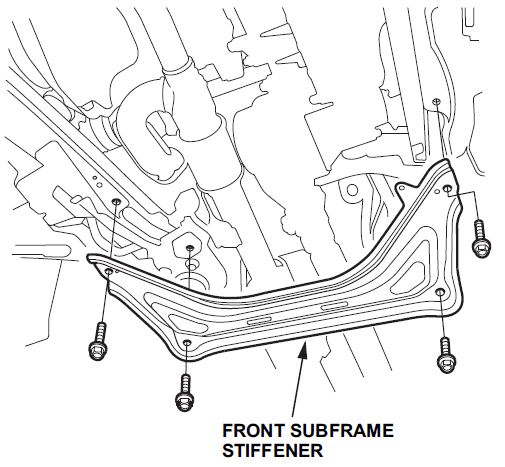
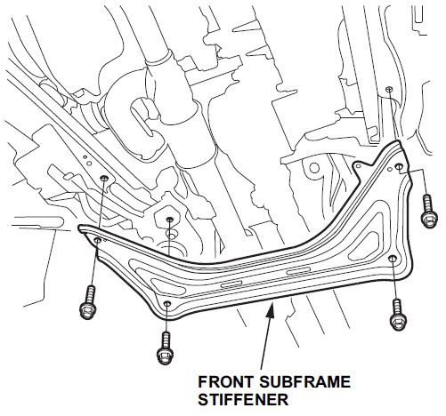
- Pilot Only: Remove the front subframe stiffener.
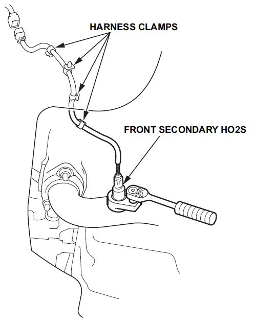
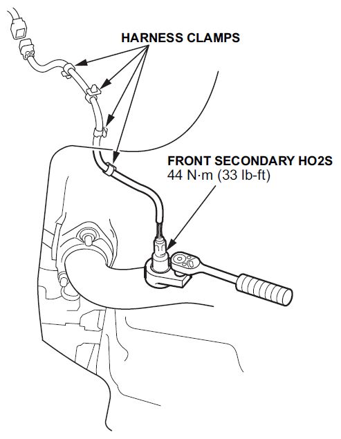
- Remove the front secondary HO2S sensor from exhaust pipe A.
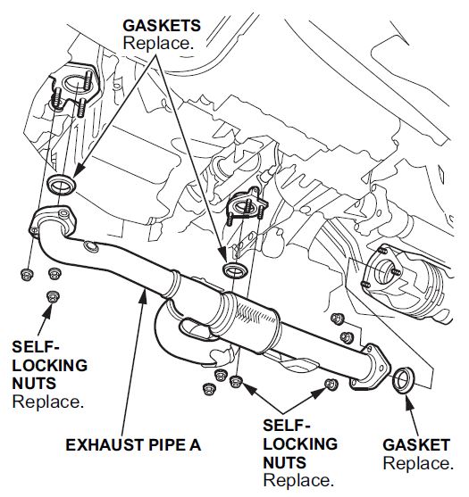
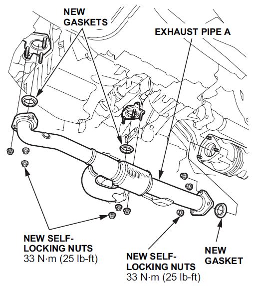
- Remove all nine nuts from exhaust pipe A, then remove the pipe.
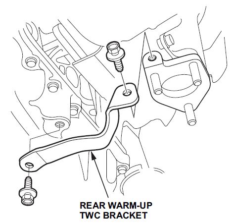
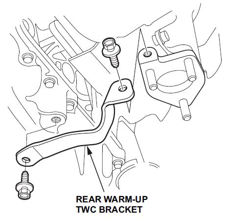
- Remove the rear warm-up TWC bracket.
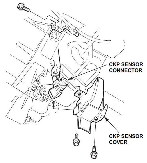
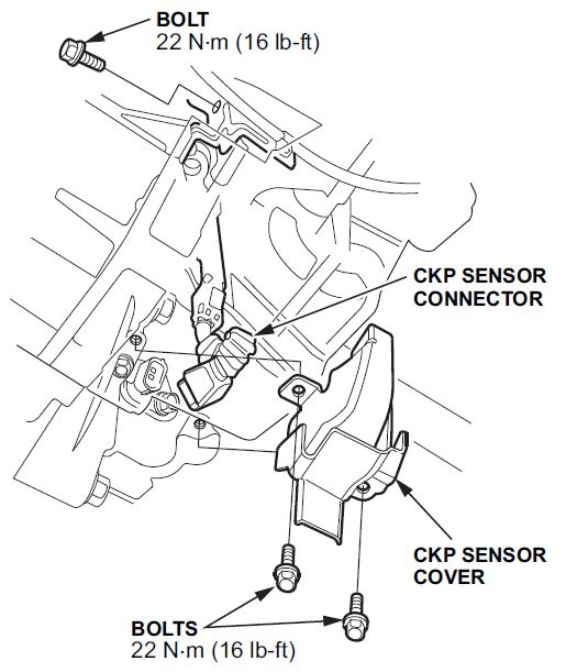
- Remove the CKP sensor cover and the bolts, then disconnect the CKP sensor connector.
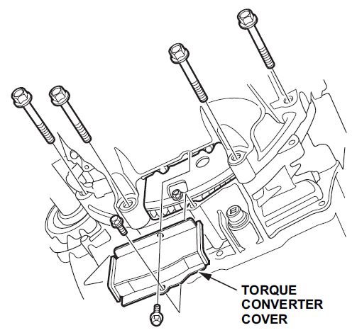
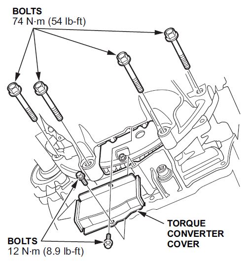
- Remove the torque converter cover and the four transmission bolts.
- Remove the oil pan bolts.
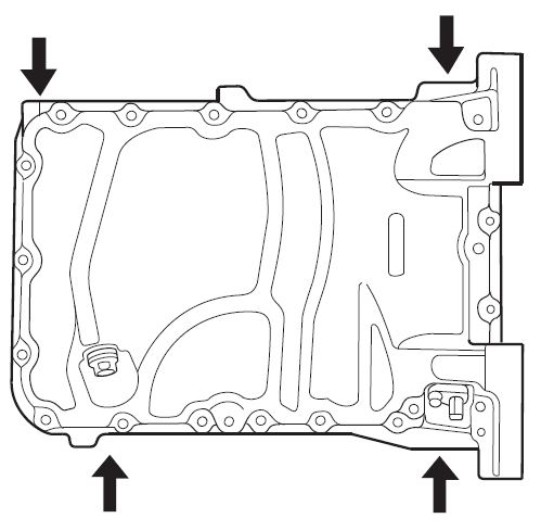
- Using a flat-blade screwdriver, separate the oil pan from the engine block at the points shown.
- Remove the oil pan.
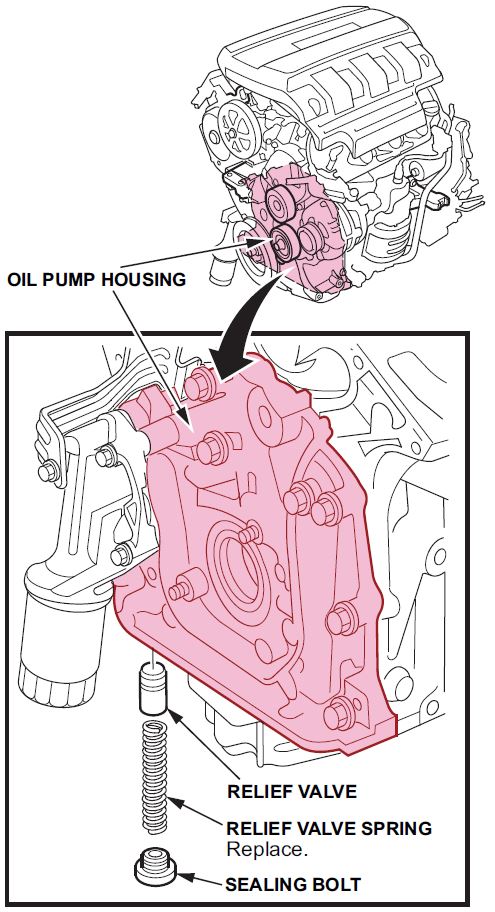
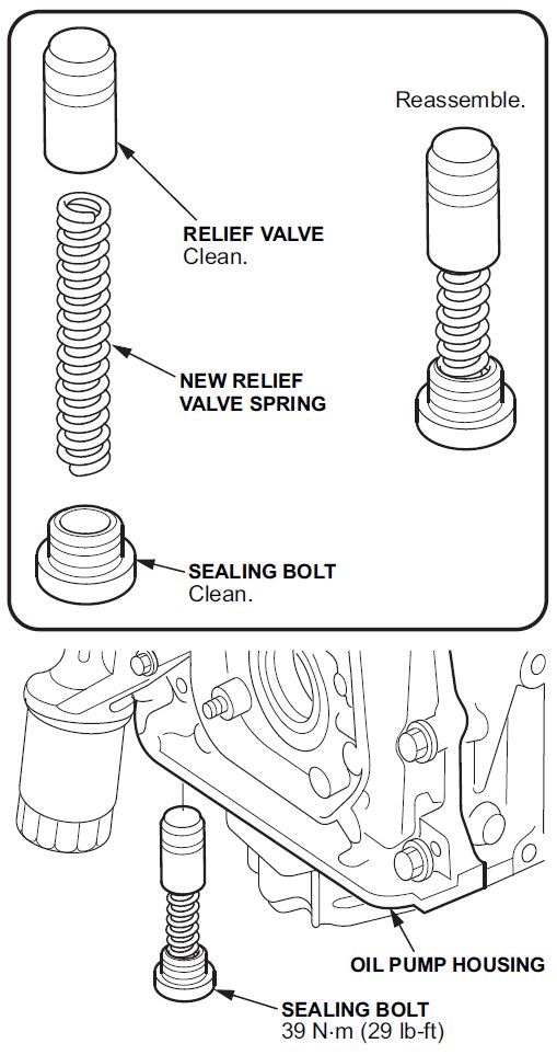
- Remove the oil pump sealing bolt, the relief valve spring, and the relief valve.
- Clean the sealing bolt and relief valve thoroughly.
NOTE: Apply Hondalock 2 to the threads.
- Insert one end of the new relief valve spring into the valve and then the other end into the sealing bolt.
Insert the three parts into the oil pump and then torque to 39 N•m (29 lb-ft).- Relief valve spring
- Remove all of the old liquid gasket from the oil panmating surfaces, the bolts, and the bolt holes.
- Clean and dry the oil pan mating surfaces.
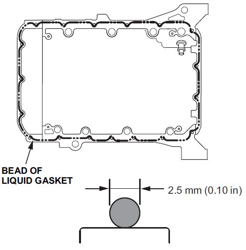
- 17. Apply liquid gasket (P/N 08718-0009 [preferred] or P/N 08718-0004) to the oil pan mating surface of the engine block and to the inside edge of the threaded bolt holes. Install the oil pan within 5 minutes of applying the liquid gasket.
NOTE:
- Apply a 2.5 mm (0.10 in) diameter bead of liquid gasket along the broken line.
- If too much time has passed after applying liquid gasket, remove the old liquid gasket and residue, then reapply new liquid gasket.
- Install the oil pan on the engine block.
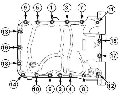
- Tighten the bolts in three steps. In the final step, torque all bolts, in the sequence shown below, to 12 N•m (8.9 lb-ft).
NOTE:
- Wait at least 30 minutes before filling the engine with oil.
- Do not run the engine for at least 3 hours after installing the oil pan.
- Install the four transmission bolts, and torque them to 74 N•m (54 lb-ft). Install the torque converter cover.
- Connect the CKP sensor connector, then install the CKP sensor cover and the bolt. Torque the bolts to 22 N•m (16 lb-ft).
- Install the rear warm-up TWC bracket. Torque the bolts to 22 N•m (16 lb-ft).
- Install exhaust pipe A using new gaskets and new self-locking nuts. Torque the nuts to 33 N•m (25 lb-ft).
- Self-locking nuts (9 required)
- Exhaust pipe gaskets (2 required)
- Pilot Only: Install the front subframe stiffener.
- Reinstall the front secondary HO2S sensor into exhaust pipe A. Torque the bolt to 44 N•m (33 lb-ft).
- Refill the engine with the recommended engine oil.
- Run the engine for at least 3 minutes, then recheck the oil level and check for leaks.
- Reset the Oil Life monitor.
- Connect the HDS.
- Turn the ignition switch to ON (II).
- Go to BODY ELECTRICAL, and select GAUGES, ADJUSTMENT, MAINTENANCE MINDER, RESET, and RESETTING THE ENGINE OIL LIFE. Then follow the prompts.
 Loading...
