| “This site contains affiliate links for which OEMDTC may be compensated” |
Job Aid
July 2020
Version 1
Combimeter Reflash Tool Instruction Manual
AFFECTED VEHICLES
| Year | Model | Trim Level |
| 2018-20 | Odyssey | ALL except LX |
| 2019-20 | Passport | ALL except Sport |
| 2019-20 | Pilot | ALL except LX |
INTRODUCTION
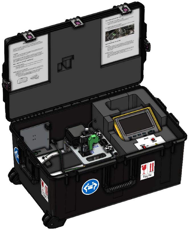
This job aid supports the combimeter reflash tool (T/N 07AAL-THRA100) used in service bulletin 20-047 Noncompliance Recall: Gauge Control Module Software Update. Be sure to review this job aid before using the tool.
SAFETY PRECAUTIONS
NOTICE
The following safety precautions have been supplied by Denso. This information alerts you to potential hazards that could hurt you or others, and cause damage to the tool, the environment, or other property.
- Always observe the following rules. Failure to do so can result in heat generation, fire, or electrical shock.
- Do not disassemble or alter this tool.
- Do not connect this tool to any voltage exceeding its ratings.
Work environment
- Do not work anywhere that water or any other liquid, could come in contact with the tool.
- Ensure the tool is safely secured on a flat surface before carrying out any work.
- Failure to do so could result in an accident.
- Only operate in a clean, well-lit environment.
- Failure to do so could result in an accident.
Check before use
- Inspect each connector for foreign material or damaged, broken, or bent pins.
- Before connecting the power cable between this tool and the source, inspect for damage.
- Before use, make sure all hinges and control knobs properly function.
- Before use, check the reflash connector for signs of abnormal wear. Also check that the connector guide is present within the unit.
- Before using the tool for the first time, make sure it is calibrated. See CALIBRATION PROCEDURE on page 6.
Handling of the product and equipment
- Avoid dropping this tool or subjecting it to a strong impact.
- When connecting any connectors, ensure correct orientation of the connector and gently insert it straight in.
- If the connector is connected in the wrong orientation, or put in or pulled out at the wrong angle, there is a risk of damaging the connector terminal and this may cause malfunctioning of this product.
- When removing any connector, hold the connector body, not the cord.
- Pulling on the cord section can break the lines in the cable over time.
- Do not lift or drag the tool by pulling on the connected power cable. When moving the tool, hold the body of the unit or the integrated handles.
- Do not apply stress to the connector of the product.
- Applying too much force could result in breaking the connector terminal, and this may cause malfunctions.
Usage restrictions
- Use this product only with approved gauge control modules.
- Always check for the proper connector prior to use to ensure you use the correct function.
- When removing the connector cover, be careful not to drop it into the product.
- Do not adjust the connector position while hinged top plate is lowered and the pogo head is down. Doing so will cause damage to the gauge control module.
Storage and maintenance of the product
- Do not expose this product to direct sunlight for long periods of time.
- Do not expose this product to extreme heat.
- Use and store this product in a dry environment.
- Do not use solvents or thinners such as benzine when cleaning.
- Doing so could cause deformation, discoloration, cracking, etc., and malfunctions may result. To clean, wipe gently with diluted neutral detergent on a soft, damp cloth.
Disposal of the product
- Discard this tool or its accessories after its useful life according to local disposal laws.
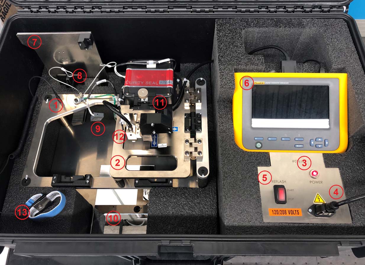
PARTS LOCATION
General View
| 1 | Reflash Jig |
| 2 | Hinged Top Plate |
| 3 | Power Indicator |
| 4 | Power Cable |
| 5 | Reflash Switch |
| 6 | Fluke Borescope |
| 7 | Calibration Plate |
| 8 | Connector Adaptor Plate |
| 9 | Cluster Power Supply |
| 10 | Inspection Mirror |
| 11 | Pogo Head Adjustment Assembly |
| 12 | Pogo Head Connector |
| 13 | Grounding Wriststrap |
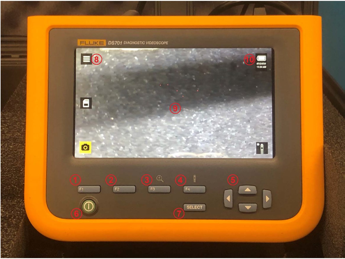
Fluke Borescope
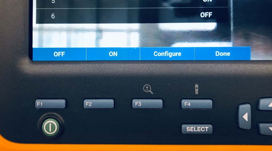
| 1 | F1 Button |
| 2 | F2 Button |
| 3 | F3 Button |
| 4 | F4 Button |
| 5 | Navigation Control Buttons |
| 6 | Power Button |
| 7 | SELECT Button |
| 8 | Menu Indicator |
| 9 | Screen |
| 10 | Battery Charge Level |
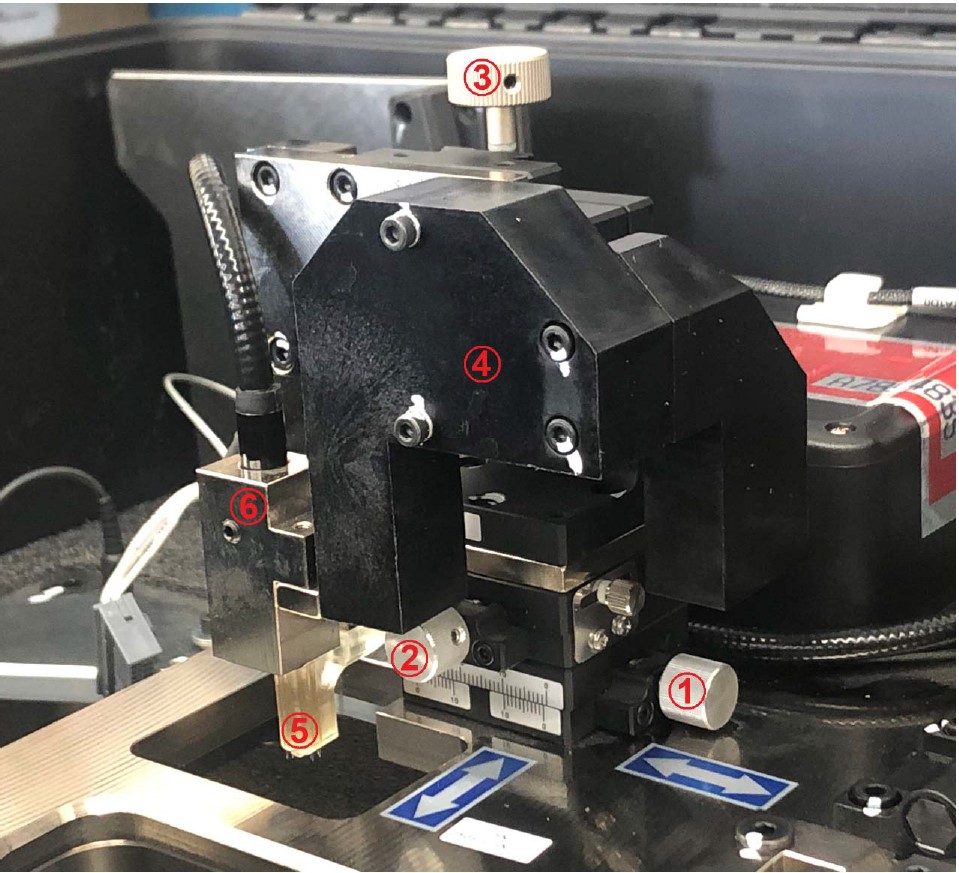
Pogo Head Adjustment Assembly
| 1 | X-Axis (Left/Right) Control Knob |
| 2 | Y-Axis (Forward/Backward) Control Knob |
| 3 | Z-Axis (Up/Down) Control Knob |
| 4 | Safety Shield |
| 5 | Pogo Head |
| 6 | Fluke Borescope Camera Head |
CALIBRATION PROCEDURE
The combimeter reflash tool must be calibrated when it first arrives at your dealership, and again if the reflash procedure continues to fail.
- Begin by powering on the combimeter reflash tool as normal, and raising the pogo head all the way up by turning the Z-axis control knob clockwise.
- Remove the master calibration plate from the case, and fully seat it into the jig. Fully lower the hinged top plate.
- Slowly lower the pogo head by turning the Z-axis control knob counterclockwise until you feel resistance or it contacts the calibration plate.
NOTICE
If the pogo head does not fit into the opening in the calibration plate, do not force the pogo head into the opening, as it may damage the tool. Call the Honda Special Tools hotline at (800) 346-6327 for assistance.
- Raise the pogo head, and adjust the X-axis and Y-axis control knobs to move the head closer to the center of the tooling. You should be moving the head away from the area where it contacted the calibration plate.
- Repeat steps 3 and 4 until the head travels into the tooling on the calibration plate without resistance, dragging, or contact. Leave the pogo head down.
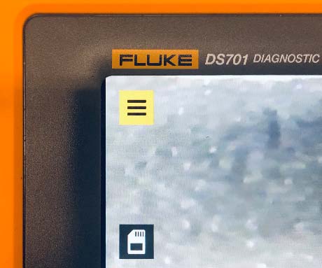
- On the Fluke borescope, use the navigation control buttons to highlight the menu indicator at the top left corner of the screen.
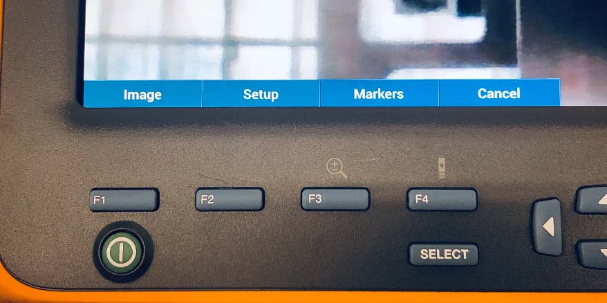
- Press the SELECT button to open the menu at the bottom left of the screen.
- Press the F3 button to select Markers.
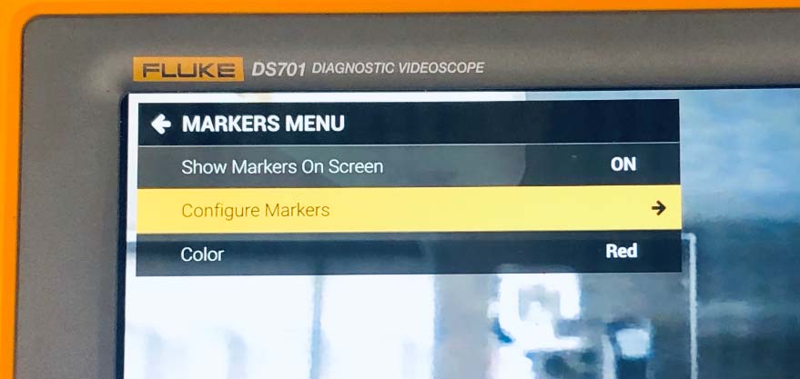
- In the MARKERS MENU, use the navigation control buttons to highlight Configure Markers.
- Press the SELECT button or the right navigation control button to select Configure Markers.
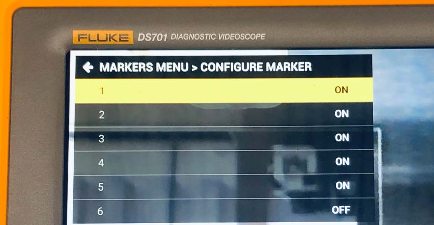
- In the CONFIGURE MARKER menu, use the navigation control buttons to highlight marker 1.
- Press the F3 button to configure marker 1
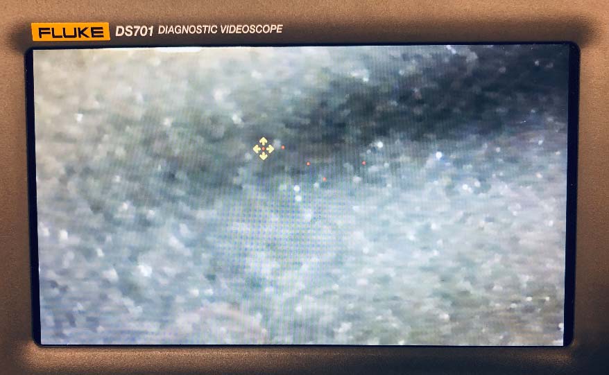
- Use the navigation control buttons to position the red marker over the hole in the calibration plate.
- Press the F4 button to go back to the CONFIGURE MARKER menu, then select the next marker to configure.
- Repeat steps 11 thru 14 until all of the markers are configured.
- When all of the markers have been configured, press the F4 button to select Done until you are back at the main screen to complete the calibration.
BASIC OPERATION
Setup / Powering On
- Open the case, and remove the power cord from its storage area. Plug the power cord into the receptacle on the control panel. If the unit does not power on, check the appropriate breaker in your facilities breaker box.
- Press the green Power button on the Fluke display, and wait for it to fully power up.
NOTE
If the Fluke display does not power up, or is showing a low battery sign on the screen, wait 1 hour with the unit plugged in to allow the internal battery to charge.
Identifying the Connector Type
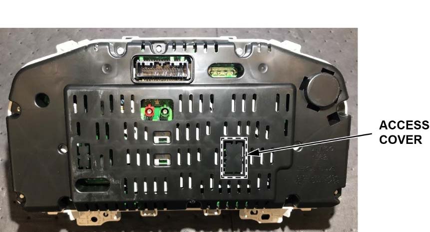
Use a small snipping tool to remove the access cover on the back of the gauge control module.
NOTICE
Do not let the access cover fall into the gauge control module. The loose access cover could result in a rattle or buzzing noise, and the difficult recovery of the cover could lead to damage to the module.
NOTE
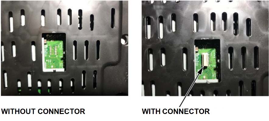
Some gauge control modules have a connector on the circuit board and some do not.
Reflashing the Gauge Control Module
To reflash the gauge control module, refer to service bulletin 20-047 Noncompliance Recall: Gauge Control Module Software Update.
TROUBLESHOOTING
General Tool Troubleshooting
| Problem | Cause | Solution |
| Power indicator is not on | Power cord is disconnected or damaged | Check cord for damage and proper engagement with the power source (wall outlet) and product. |
| Power indicator is on, but Fluke borescope is not powering on | Battery within Fluke borescope is exhausted | Leave the unit plugged in, and wait about 1 hour to charge. |
| Fluke borescope displays battery icon
| Battery within Fluke borescope is exhausted | Leave the unit plugged in, and wait about 1 hour to charge. |
| Fluke screen is dim or turned off | Fluke backlight setting is too low or off | Press the backlight button (F4) to open the backlight setting, and use the arrows to increase brightness. |
| Fluke screen is too bright | Fluke backlight setting is too high | Press the backlight button (F4) to open the backlight setting, and use the arrows to decrease brightness. |
Reflashing Gauge Control Modules with a Connector
| Problem | Cause | Solution |
| Gauge control module is booting normally instead of reflash sequencing | Connection between gauge control module and combimeter reflash tool is broken | Make sure the power and reflash cables are properly connected to the gauge control module. Also, make sure the reflash adaptor is properly in place. |
| Gauge control module is not turning on during reflash process |
Reflashing Gauge Control Modules without a Connector
| Problem | Cause | Solution |
| Gauge control module is booting normally instead of reflash sequencing | Probe head is misaligned or damaged | 1. Raise the pogo head, and try to align the probe head. Try the flash process again.
2. If the problem continues, inspect the probe head for damage, such as a bent or missing pin. 3. If the problem still continues, recalibrate the pogo head position. See Calibration Procedure on page 9. |
| Gauge control module is not turning on during reflash process | Gauge control module power cable is ajar or damaged | Verify the power connector is fully seated into the gauge control module. |
NOTE
If you need further assistance, call the Honda Special Tools hotline at (800) 346-6327.
REPLACEMENT COMPONENTS
| Part Name | Part Number | Description |
| Pogo head, Reflash | 07AAL-THRA110 | Pogo head for reflashing non-populated GDC meters |
| Cable, C13 to Type B | 07AAL-THRA130 | Power Cable (110 V) |
| Display, Borescope | 07AAL-THRA160 | Fluke main display and case with buttons |
| Cable, Borescope Power | 07AAL-THRA170 | Power cable for Fluke borescope |
| Calibration, Pogo head | 07AAL-THRA180 | Calibration plate for aligning pogo head for mastering of borescope |
| Wriststrap, ESD Ground | 07AAL-THRA190 | ESD wriststrap and cable |
| Sheet, Hole Seal | 07AAL-THRA120 | Felt to apply to cover reflash hole (service part with size) |
| Hinge, Adjustable Torqu | 07AAL-THRA1B0 | Tension hinge |
| Card, SMART Reflash | 07AAL-THRA1D0 | Cable from SMART reflash unit to adapter board |
| Card, SMART Reflash | 07AAL-THRA1E0 | Adapter board and connection to meter/cable |
| Alignment, GDC | 07AAL-THRA1F0 | Plastic alignment tool for adapter board |
| Sub-cable, Combimeter | 07AAL-THRA150 | 32 pin meter connector |
| Unit, SMART Reflash | 07AAL-THRA140 | SMART Reflash Unit (with SD card software installed and cyber security measures in place) |
NOTE
To order replacement parts, call the Honda Special Tools hotline at (800) 346-6327.
TOOL SPECIFICATIONS
| Item | Specification | |
| Size | 31.3 in. (L) x 20.4 in. (W) x 13.8 in. (H)
79.5 cm (L) x 51.8 cm (W) x 35.1 cm (H) | |
| Weight | Approx. 59 lbs.(22.7 kg) | |
| Operating Environment | Operating Temperature | 32 °F to 122 °F (0 °C to 50 °C) |
| Storage Temperature | -4 °F to 158 °F (-20 °C to 70 °C) | |
| Operating Humidity | 10 to 90% (No condensation) | |
| Main Power Supply Voltage | 95 to 264 VAC at 47 to 63 Hz | |
| Power Consumption | Normal Operation 50W (120 VAC)
Max. 1.2kW (120 VAC) | |
| Gauge Control Module Output Voltage | 11-13 VDC | |
| Fluke Borescope Input Voltage | 5.0VDC | |
STORAGE
This tool should be stored in accordance with the following:
- Power the unit down fully using the power button on the Fluke borescope and unplugging the power supply cable.
- The Z-axis control knob should be lowered down approximately 3 full rotations from its highest position.
- If it is too high, you risk the case lid damaging it when being closed.
- If it is too low and is not raised prior to the insertion of a gauge control module when next used, the head will collide with the gauge control module, causing damage to the head.
- Make sure there is no gauge control module in the reflash jig when the hinged plate is lowered.
- The calibration plate connector alignment tool, gauge control module power supply cable, and power cable should be stored in their respective storage locations.
- Close the case lid and latch all points around the lid.
- Store the closed case in a cool, dry area, away from direct sunlight.
END
 Loading...
Reprogramming
i-HDS Diagnostic Software and J2534 Reprogramming Software
Honda J2534 Pass-Thru User Guide
Honda J2534 Pass-Thru Software Download
i-HDS Diagnostic Software and J2534 Reprogramming Software
American Honda Motor Co., Inc. ("Honda
 ") offers the i-HDS (Honda
 Diagnostic System) software suite for the diagnosis and repair of electronic systems on Honda
 and Acura
 automobiles, and for the reprogramming of electronic control units (including, but not limited to, ECMs and PCMs). This software provides access to all Honda
 and Acura
 vehicle systems (access to the immobilizer security system requires a Security Professional level software subscription and Vehicle Security Professional [VSP] registration with NASTF). To use the i-HDS software, you need to purchase one of our convenient subscription options. In addition, you will need a pass-thru Vehicle Communication Device (VCI) that is compliant with SAE J2534-1 and J2534-2 in order to communicate with the vehicle
Vehicle Communication Interfaces (VCI)
The i-HDS software supports the use of a generic pass-thru VCI that is compliant with SAE J2534-1 and J2534-2. However, Honda recommends the Denso DST-i or the Bosch MVCI for use on Honda
 and Acura
 vehicles, as Honda
 has worked closely with these manufacturers to ensure their hardware and our software interact safely and within the J2534-1 and -2 specifications, for both diagnostics and reprogramming. If you choose to use a generic VCI, please carefully consider the customer and technical support options you will receive from your chosen device supplier. Honda
 does not provide technical or customer support for generic VCI devices.
The VCI Application Table below lists devices that either are approved and supported by Honda or are known to have completed and passed an independent, exhaustive validation program with our i-HDS software suite.
| VCI Name | Manufacturer | Version Information | Notes | |
|---|---|---|---|---|
| Firmware | J2534 API | |||
| DST-i | DENSO | 2.02.0002* | 04.04 | This is the current generation VCI used by Honda and Acura and Acura dealers. Honda dealers. Honda routinely validates the functionality and provides customer support for this device. routinely validates the functionality and provides customer support for this device. |
| DST-nano | DENSO | 2.02.0002* | 04.04 | This is the current generation VCI used by Honda Canada Inc. Honda Canada Inc. Honda and Acura and Acura dealers. Honda dealers. Honda routinely validates the functionality and provides customer support for this device. routinely validates the functionality and provides customer support for this device. |
| MVCI | Bosch | 3.01.60* | 04.04 | This is the previous generation VCI used by Honda and Acura and Acura dealers. Honda dealers. Honda routinely validates the functionality and provides customer support for this device. routinely validates the functionality and provides customer support for this device. |
| MongoosePro Honda |
Drew Technologies | 1.9.5** | 04.04 | This company has completed an independent i-HDS validation and claims it to function with the i-HDS software. Honda does not provide ongoing validation, nor customer support for this device. does not provide ongoing validation, nor customer support for this device. |
| d-briDGe Pro | Dearborn Group | 3.303** | 04.04 | This company has completed an independent i-HDS validation and claims it to function with the i-HDS software. Honda does not provide ongoing validation, nor customer support for this device. does not provide ongoing validation, nor customer support for this device. |
* These versions may have been superseded. Honda provides the latest supported versions to current i-HDS subscribers.
** Version used in validation program. See Terms and Conditions and Important Notice Regarding Reprogramming below for more details.
Reprogramming with the J2534 Rewrite Application in i-HDS
Included in the i-HDS software suite is a new reprogramming application called J2534 Rewrite. This application is made available to all subscribers of the i-HDS software suite and replaces the previous generation software, J2534 Honda Pass-thru Reprogramming Software.
This new application is compatible with generic VCIs that comply with SAE J2534. It must be used to reprogram any Honda /Acura
 vehicle equipped with ECUs that support reprogramming. Refer to the table below for legacy applicability for the programming of ECMs and PCMs. Though system dependent, late-model vehicles may be equipped with other ECUs that support reprogramming as well, e.g. ABS or VSA. J2534 Rewrite must be used to reprogram these control modules, as instructed in an applicable service bulletin.
As shown in this table, not all legacy Honda /Acura
 models are equipped with a reprogrammable ECM/PCM. Furthermore, all 2007 and later models not listed in the table are fully supported with this application.
DST-i Information:
MVCI Information:
- J2534 Pass-Thru Programmer: TOPDON RLink J2534 is an advanced diagnostic and reprogramming tool that support all J2534 protocols, as well as D-PDU, CAN-FD and DoIP, ensuring compatibility with a wide range of modern vehicles. It offers extensive versatility with support for over 17 major automotive brands, including Chrysler, Ford, GM, Nissan, Toyota
 , Honda
 , Subaru, Land Rover/Jaguar, Volvo, Wuling, Volkswagen
 , Mercedes-Benz, and BMW
 , and so on, enjoy dealership-level functions at your fingertips
 - All-in-One OEM Diagnostics: This J2534 ECU programming tool elevates your automotive repair capabilities to new heights by delivering complete OEM diagnosis. Boasting comprehensive full-system diagnostics, intuitive repair guides, advanced ECU programming and coding, common reset services, a vast library of repair information and more, this all-in-one solution empowers technicians to effortlessly tackle complex vehicle issues with ease
- Proven Performance You Can Trust: Backed by over 10000 real vehicle tests and benefit from a wealth of practical experience, this OEM reprogramming tool guarantees stable and exceptional performance. Supported by TOPDON's dedicated technical experts with in-depth knowledge of both auto repair and J2534 Pass-Thru programming, the RLink J2534 provides prompt and professional assistance, ensuring a smooth setup and reliable compatibility
- Integrated Excellence, Always Up-to-Date: Featuring the exclusive RLink Platform to provide a streamlined experience with one-click driver installation and management, ensuring flawless integration with your OE software, maintaining the original performance quality. The built-in operation guide makes mastering OE software quick and easy, so you can get started right away. Plus, with lifetime free updates, your diagnostics will stay current with the latest drivers and innovations
- Efficiency Meets Versatility: Engineered to support three CAN channels simultaneously - CAN FD and CAN-CC included, giving you the edge in fast troubleshooting. To perfectly synchronized with the OE software, please diagnose with active subscriptions and make sure your computer system is running a compatible 64-bit Windows version (7, 8, 10 or later) to fully leverage the power of RLink J2534. *We don't provide extra OE software
- 【J2534 PROTOCOL WITH SMARTLINKC】 LAUNCH X431 PRO3S+ ELITE scan tool with newly upgraded smartlinkC V2.0. The SmartLinkC is a communication interface supporting J2534 specifications. Of course, it also can be used as a J2534 PassThru device, working together with the PC installed with the OEM diagnostic software to perform the J2534 protocol.J2534 protocol is the only solution for problems ranging from driveability and loss of power to poor fuel economy.
- 【INTELLIGENT TOPOLOGY MAP TO FASTER FULL SYSTEMS DIAGNOSIS】 X431 PRO3S+ELITE bidirectional scan tool with new-added intuitive topology mapping. Harnesses intuitive topology mapping for comprehensive visualization of the vehicle all system. It shows all available control units in different colors, the numbers of system, the scanned system, and the scan results, bringing maximum convenience & superfast speed for you to do swift diagnosis & high-level repairs.
- 【TOP HARDWARE CONFIGURATION, UPGRADED OF LAUNCH X431 PRO3S+】 LAUNCH X431 PRO3S+ELITE diagnostic scanner possess with Android 10.0 OS; CPU 4-Core Processor, 2.0 GHz. Greatly increased the speed of running multiple task. 2.4GHz/5GHz; 6300mAh/7.6V stronger battery capacity; 10.1 Inch Touchscreen with 8MP camera; AUTO VIN; 4GB+64GB storage memory; 20X faster transmission rate, save more vehicle documents and customer data; Supports 25+ Software Languages, such as EN, DE, FR, SP nd JP and so on.
- 【3000+ ACTIVE TEST/BI-DIRECTIONAL CONTROL LAUNCH SCANNER】 LAUNCH X431 PRO3S+ELITE HD automotive scanner is a cost-effective bidirectional scanner that deserves owned by every repairing DIYers and mechanics. You can easily send command signal at fingertips from the scanner to various module actuators to test component integrity and functionality in minutes or even seconds to tell if replacement or repair is needed.
- 【COMPLETE 60+ HOT RESETS, CALIBRATION, INITIALIZATION, RELEARN】 LAUNCH X431 PRO3S+ELITE SmartLinkC escaner automotriz professional enjoys 60+ special service, such as Oil Reset, ABS brake bleed, EPB, SAS, BMS, Suspension, Injector reset, Power Balance, Turbo Calibration, VGT, Transmission Adaption, Throttle Adaptation, matching and etc. rigorous on-site testing has been performed to ensure 100% availability.
- ALL OF THE J2534 PROTOCOLS - This single unit has all of the protocols you need for your OEM J2534 reprogramming and diagnostics including the latest in DoIP and CanFD
- J2534 TECHNICAL SUPPORT - FREE for the life of the tool. Staffed by technicians who understand vehicle repair and J2534 Pass‑thru
- TOOLBOX WITH OEM APPLICATION DESCRIPTIONS - educational video tutorials and real-time news – Giving you the confidence and up-to-date knowledge to get the job done
- J2534 v05.00 API - The newest version of J2534 to give you the latest in pass-thru technology
- FUTURE PROOF WITH 4 CAN CHANNELS - Going beyond the 3 required by select Chrysler/FCA models, CarDAQ-Plus 3 also provides a 4th to meet the needs of future OEM applications
- 🌐【Works with Autel Elite II Elite MS908 MS908S Pro II MS908CV II MK908P MK908 Pro II】Autel J2534 work with these tools to program ECUs on specific BM.W/ BE.NZ for specific functions. ★★NOTE: J2534 CANNOT directly work with these single devices. After you received the J2534, you HAVE TO send us both the S/N(12 digits) of your scanner MS908S(etc.) and J2534. So, technically, Autel engineers can help you bind J2534 with your devices. If need any supports, contact us via: 🚘auteldirect @ outlook. com🚘.
- 🌐【SAE J2534-1 & J2534-2 Standards】Autel MaxiFlash Elite J2534 is a fully compliant SAE J2534-1 & SAE J2534-2 (March 2006) device, which performs standard PassThru J2534 functionality: Compatible with for Toyota
 Techstream, Volvo VIDA, Honda
 HDS, Jaguar-Land Rover IDS and BM.W 3G for OEM diagnostics. Autel MaxiFlash J2534 is also specially designed to provide users with P-C communication and ECU reprogramming capabilities on any modern vehicle diagnostic bus, reliability and flexibility.
 - 🌐【High-speed Transmission Speed】Autel MaxiFlash Elite Reprogramming Device J2534 supports simultaneous communication definition in J2534-1, running 3 protocols at the same time, which greatly improves reprogramming and diagnostic speed. Embedded with the ARM9 Dual-core processor (clocked up to 500MHz), which further boosts the communicating speed to save more times and win more business.
- 🌐【Multiple Devices Connected with P-C】Autel MaxiFlash Elite J2534 also supports multiple device connections to the P-C, which can operate diagnostic and reprogramming functions on more than one vehicle at the same time. Autel MaxiFlash Elite J2534 built-in wireless and data storage, which can update via Internet. It also ensures quickly reprogramming even the newest controllers.
- 🌐【Extensive Compatibility】Autel MaxiFlash J2534 is compatible with Toyota
 Techstream, Volvo VIDA, Honda
 HDS, Jaguar-Land Rover IDS and BM.W 3G for OEM diagnostics. To check compatibility, please contact 🚘auteldirect @ outlook . com🚘 directly for satisfaction-guaranteed support!
- CUSTOM-DESIGNED FOR USE WITH FORSCAN: Works with all FORScan compatible vehicles and is recommended by the FORScan Team
- DEALERSHIP-LEVEL DIAGNOSTICS: OBDLink EX supports all Ford protocols, modules, and advanced features of FORScan
- ELECTRONIC SWITCH allows FORScan to access all CAN buses simultaneously and enables advanced functions not possible with “toggle switch” adapters
- MAXIMUM THROUGHPUT -- up to 20 times faster than “toggle switch” adapters
- ROCK-SOLID CONNECTION avoids data corruption and dropped packets
- 🌎【Autel All-in-1 Reprogramming Tool】As an OEM Vehicle interface for multiple makes, Autel J2534 pass-thru programmer is a multi-functional programming and communication device. Work with Autel MS909 Ultra Lite Elite 2 Pro MS909 MS909CV MS909EV to directly program on Merce.des-Be.nz & BM.W. Autel MaxiFlash VCI also works with P-C to download OEM vehicle software, seamlessly conduct OE-level diagnostic-programming-coding. Enhanced multi-protocol: SAE J2534/ CAN FD/ DoIP/ D-PDU/ RP1210, Autel Maxiflash VCI J2534 is a must have aftermarket programming device for any mechanic/ technician in the programming wo.rld!
- 📢【Kind Tips】After purchasing the J2534, you need to update the firmware first. Steps: ✅𝟭. Access to Autel official website > click "Support" - "Download" > download "Maxi P-C Suite" APP ✅𝟮. connect J2534 and compu-ter via USB Cable ✅𝟯. Install "Maxi P-C Suite" APP on the compu-ter and update to the latest version > go to the vehicle website to purchase the corresponding OEM software for use. 📢Note: J2534 is only compatible with Windows compu-ters, and OEM software needs to be purchased.
- 🌎【Compatible with Autel Elite II Pro Ultra Lite MS909 MS909CV MS909EV & P-C/ WIND.OWS】This 2025 latest Autel J2534 Pass-Thru VCI is 100% compatible with Autel Elite II Pro Ultra Lite MS909 MS909CV MS909EV to perform advanced functions from diagnose to programming. Besides, it can connect to P-C with Easy Steps: 1) Connect to P-C via a USB cable 2) download OEM vehicle software 3) Start Diagnose. Take For.d for example, you can download OEM software on mot.orcraft.erservi.ce website, such as: For.d Diagnostic Software downloads, As B.uilt Data, Updated Cali.bration information, then use different software do relevant features.
- 🌎【Enhanced Protocol: CAN FD/DoIP/D-PDU/RP1210/J2534】Autel MaxiFlash JVCI is a blueto.oth communicate device, it supports latest CAN FD DoIP CAN protocols, compliant with automotive D-PDU/ J2534/ RP1210 standards. It can perform standard PassThru J2534 functions: compatible with Toyota
 Techstream, Volvo VIDA, Honda
 HDS, Jaguar Land Rover IDS and BM.W 3G for OEM diagnostics. CAN FD protocol is mainly for GM 2019+, DoIP protocol is mainly for Volvo 2018+, for L-and Rover/for Jaguar 2017+, for BM.W F chassis and G chassis.
 - 🌎【ECU Programming Coding】Tailored to ECU programming & coding, Autel J2534 Pass-Thru VCI can communicate effectively with the ECU across different vehicle makes and models. After you purchased OEM software, J2534 pass thru programmer can work with P-C: Update vehicle software to the latest version, optimize the histo.rical le.gacy of the car's old version, Replace existing software/ firmware, reprogram component after replacement.
Last update on 2025-05-08 / Affiliate links / Images from Amazon Product Advertising API
This product presentation was made with AAWP plugin.

