| “This site contains affiliate links for which OEMDTC may be compensated” |
A09-023
April 11, 2009
Applies To:
2003–07 Element – ALL
2008 Element 2WD – From VIN 5J6YH1…8L000001 thru 5J6YH1…8L017044
2008 Element 4WD – From VIN 5J6YH2…8L000001 thru 5J6YH2…8L019754
Clanking or Knocking Noise From the Front Suspension While Going Over Bumps
SYMPTOM
The front suspension clanks or knocks while going over bumps.
PROBABLE CAUSE
The compliance bushings in the front lower arms are cracked.
CORRECTIVE ACTION
Replace both front compliance bushings, and do a wheel alignment.
PARTS INFORMATION
| Flange Nut (’07–08 models, two required): P/N | 90002-S10-000 | H/C 4977401 |
| Front Compliance Bushing Kit (Includes left and right bushings): P/N | 04513-SCV-000 | H/C 9125105 |
| Lower Arm Flange Bolt (’07–08 models, two required per side): P/N | 90118-SCV-A00 | H/C 8401093 |
| Upper Arm Clip (two required): P/N | 90701-SX0-003 | H/C 4635033 |
TOOL INFORMATION
| Ball Joint Remover, 28 mm: T/N | 07MAC-SL00200 | H/C 3635075 |
| Ball Joint Remover, 32 mm: T/N | 07MAC-SL00100 | H/C 3635083 |
| Ball Joint Thread Protector, 12 mm: T/N | 07AAF-SDAA100 | H/C 7335821 |
| Ball Joint Thread Protector, 14 mm: T/N | 071AF-S3VA000 | H/C 6603849 |
| Bushing Driver: T/N | 07AAF-SVAA100 | H/C 8531204 |
| Bushing Receiver Set: T/N | 07AAF-SVAA200 | H/C 8549206 |
WARRANTY CLAIM INFORMATION
In warranty: The normal warranty applies.
| OP# | Description | FRT |
| 4161E9 C | Replace both front lower compliance bushings.
Add for doing an alignment. | 1.0
0.6 |
Failed Part: P/N 51391-SCV-A02 H/C 8866089
Defect Code: 02101
Symptom Code: 04201
Skill Level: Repair Technician
Out of warranty: Any repair performed after warranty expiration may be eligible for goodwill consideration by the District Parts and Service Manager or your Zone Office. You must request consideration, and get a decision, before starting work.
DIAGNOSIS
Listen for clanking or knocking in the front suspension while driving over bumps:
- If you hear the noise, or see that the bushing is cracked, go to REPAIR PROCEDURE.
- If you don’t hear the noise, continue with normal troubleshooting.
REPAIR PROCEDURE
- Raise the front of the vehicle, and support it with safety stands in the proper locations.
- Remove the front wheels.
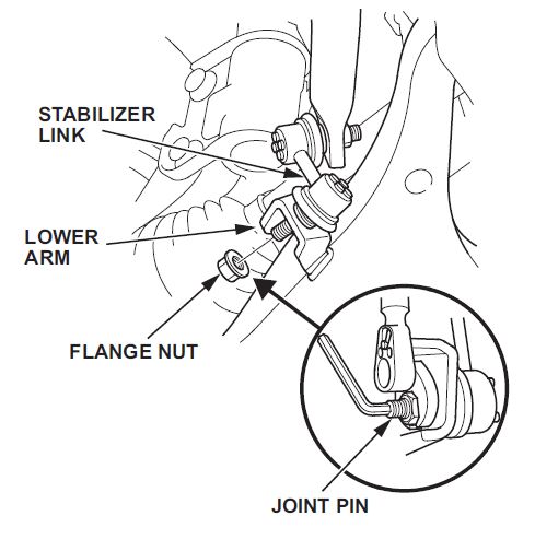
- Remove the flange nut while holding the joint pin with a hex wrench, and disconnect the stabilizer link from the lower arm.
NOTE: Use a new flange nut during reassembly.
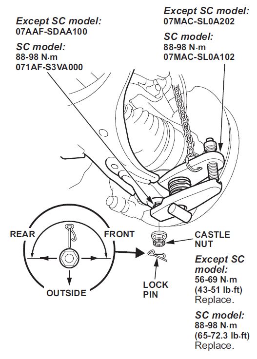
- Remove the lock pin from the knuckle ball joint, then remove the castle nut.
NOTE: During installation, insert the lock pin as shown after tightening the new nut.
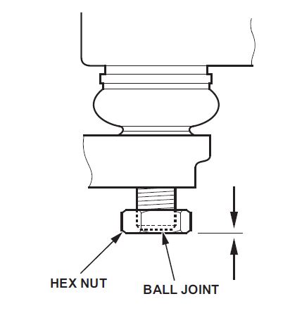
- Install a hex nut or the ball joint thread protector onto the threads of the ball joint. Make sure the nut is flush with the ball joint pin end to prevent damage to the threaded end of the ball joint pin.
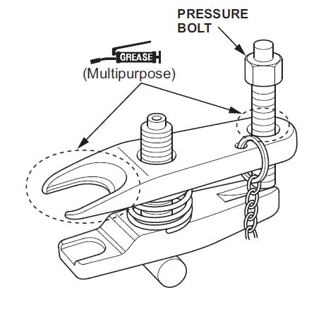
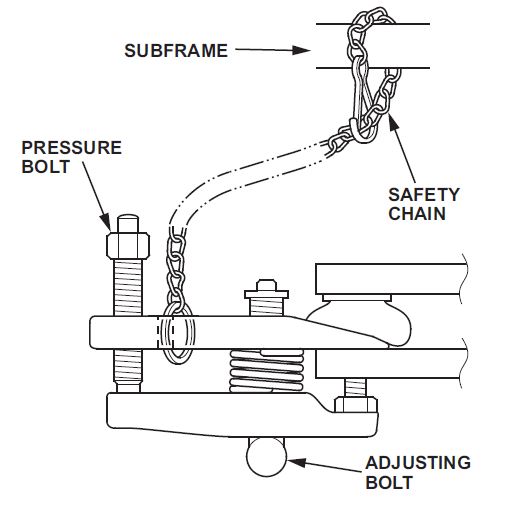
- Apply grease to the ball joint remover on the areas shown. This will ease installation of the tool and prevent damage to the pressure bolt threads.
- Loosen the pressure bolt, and install the ball joint remover as shown. Insert the jaws carefully, making sure not to damage the the ball joint boot. Adjust the jaw spacing by turning the adjusting bolt.
NOTE: Fasten the safety chain securely to a suspension arm or the subframe. Do not fasten it to a brake line or a wire harness.
- After adjusting the adjusting bolt, make sure the head of the adjusting bolt is in the position shown to allow the jaw to pivot.
- Using a wrench, tighten the pressure bolt until the ball joint pin pops loose from the ball joint connecting hole. If necessary, apply penetrating type lubricant to loosen the ball joint pin.
NOTE: Do not use pneumatic or electric tools on the pressure bolt.
- Remove the ball joint remover, then remove the hex nut or the ball joint thread protector from the end of the ball joint pin, and pull the ball joint out of the ball joint connecting hole. Inspect the ball joint boot, and replace it if damaged.
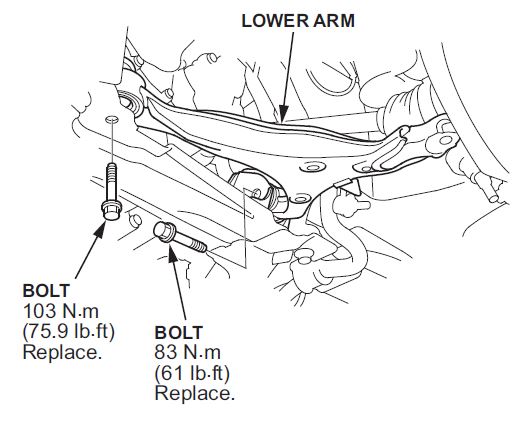
- Remove the flange bolts, then remove the lower arm.
NOTE: Use new flange bolts during reassembly.
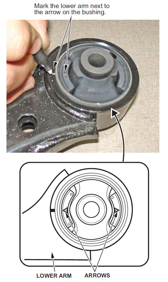
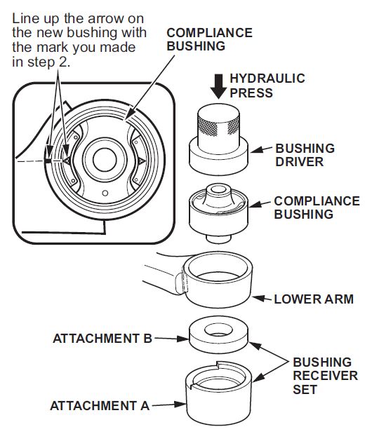
- Mark the lower arm at the location of the arrow on the compliance bushing.
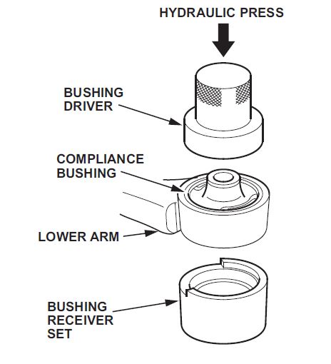
- Press out the compliance bushing from the lower arm using the bushing driver, the bushing receiver set, and a hydraulic press.
NOTE: Be careful not to damage the inside of the bushing opening on the lower arm.
- Clean the mating surfaces of the new compliance bushing and the lower arm.
- Align the arrows of the new bushing with the mark made in step 2, then press the bushing into the lower arm using the bushing driver, the bushing receiver set, and a hydraulic press.
- Repeat steps 3 thru 15 on the other lower arm.
- Reinstall the front lower arms, and note these items:
- First install all the components, and lightly tighten the bolts and nuts, then lower the vehicle to the ground to load the suspension before fully tightening the fasteners to the specified torque.
- Be careful not to damage the ball joint boot when connecting the lower arm to the knuckle.
- Before connecting the knuckle ball joint to the lower arm, degrease the threaded section and tapered portion of the ball joint pin, the ball joint connecting hole, the threaded section, and the mating surfaces of the castle nut.
- Torque the castle nut to the lower torque specification, then tighten it only far enough to align the slot with the ball joint pin hole. Do not align the castle nut by loosening it.
- Before installing the wheel, clean the mating surfaces of the brake disc and the inside of the wheel.
- Check the wheel alignment, and adjust it if necessary.
- Test-drive the vehicle over bumps to make sure the noise is gone.
 Loading...
