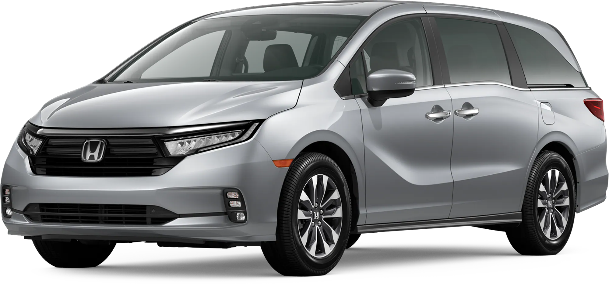
A23-046
June 16, 2023
Version 1
Safety Recall: 2018–23 Odyssey Install FAKRA Service Cables at MOST Bus Network
AFFECTED VEHICLES
| Year | Model | Trim Level | VIN Range |
| 2018–2023 | Odyssey | ALL except LX | Check iN for VIN Eligibility |
BACKGROUND
A coaxial cable terminal was not manufactured to proper specifications. An improperly manufactured terminal may lead to poor communication in the MOST bus network which can potentially affect the quality of audio sound and/or potentially cause the rearview camera to work intermittently or go blank when the vehicle is in the reverse gear.
CUSTOMER NOTIFICATION
Owners of affected vehicles will be sent a notification of this safety recall.
Do an iN VIN status inquiry to verify eligibility.
Some vehicles affected by this campaign may be in your new or used vehicle inventory.
Failure to repair a vehicle subject to a recall or campaign may subject your dealership to claims or lawsuits from the customer or anyone else harmed as a result of such. To see if a vehicle in inventory is affected by this safety recall, do a VIN status inquiry before selling it.
NOTE: ALL VEHICLES AFFECTED on this action must be repaired independent if the vehicle was repaired previously using the following Service Bulletins:
- 20-049, 2021 Odyssey: Popping or Crackling from the Speakers; No Sound from the Audio System; Network Loss Message and/or Display Issues
- 21-013, Warranty Extension: 2018–20 Odyssey MOST Bus Network Connectors
CORRECTIVE ACTION
Install the FAKRA splice repair service cables, and splice boxes.
PARTS INFORMATION
| Part Name | Part Number | Quantity |
| Splice Box | 39817-THR-305 | 7 Splice boxes (14 halves) |
| FAKRA Splice repair service cable (Green) | 39165-THR-AB0 | 3 |
| FAKRA Splice repair service cable (Red) | 39165-THR-AA0 | 3 |
| FAKRA Splice repair service cable (Blue) | 39165-THR-AC0 | 1 |
TOOL INFORMATION
| Tool Name | Tool Number | Quantity |
| Straight FAKRA Puller | 07AAC-THRA200 | 1 |
| Cargo Cap Screw Socket | 07AAA-SEPA100 | 1 |
| Digital Borescope | BK5600DUAL55 | 1 |
FAKRA CONNECTOR HOUSING DISASSEMBLY/FAKRA SPLICE REPAIR SERVICE CABLE ASSEMBLY PROCEDURE
In PDF Bellow…
Recall EEL & ZEM – Rearview Image May Not Display – 2018-2023 Honda Odyssey, 2019-2022 Pilot, & 2019-2023 Passport
Safety Recall: 2018-2023 Honda Odyssey Install FAKRA Service Cables at MOST Bus Network
Remedy Instructions and TSB
RCRIT-23V431-0884.PDF 5029.222KB
Latest Recalls Documents

- J2534 Pass-Thru Programmer: TOPDON RLink J2534 is an advanced diagnostic and reprogramming tool that support all J2534 protocols, as well as D-PDU, CAN-FD and DoIP, ensuring compatibility with a wide range of modern vehicles. It offers extensive versatility with support for over 18 major automotive brands, including Chrysler, Ford, GM, Nissan, Toyota, Honda, Subaru, Land Rover/Jaguar, Volvo, Wuling, Volkswagen/Audi, Mercedes-Benz, and BMW. NOTE: Not compatible with Ford IDS diagnostic software
- All-in-One OEM Diagnostics: This J2534 ECU programming tool elevates your automotive repair capabilities to new heights by delivering complete OEM diagnosis. Boasting comprehensive full-system diagnostics, intuitive repair guides, advanced ECU programming and coding, common reset services, a vast library of repair information and more, this all-in-one solution empowers technicians to effortlessly tackle complex vehicle issues with ease. *Not compatible with 24V vehicles
- Proven Performance You Can Trust: Backed by over 10000 real vehicle tests and benefit from a wealth of practical experience, this OEM reprogramming tool guarantees stable and exceptional performance. Supported by TOPDON's dedicated technical experts with in-depth knowledge of both auto repair and J2534 Pass-Thru programming, the RLink J2534 provides prompt and professional assistance, ensuring a smooth setup and reliable compatibility
- Integrated Excellence, Always Up-to-Date: Featuring the exclusive RLink Platform to provide a streamlined experience with one-click driver installation and management, ensuring flawless integration with your OE software, maintaining the original performance quality. The built-in operation guide makes mastering OE software quick and easy, so you can get started right away. Plus, with lifetime free updates, your diagnostics will stay current with the latest drivers and innovations
- Efficiency Meets Versatility: Engineered to support three CAN channels simultaneously - CAN FD and CAN-CC included, giving you the edge in fast troubleshooting. To perfectly synchronized with the OE software, please diagnose with active subscriptions and make sure your computer system is running a compatible 64-bit Windows version (7, 8, 10 or later) to fully leverage the power of RLink J2534. *We don't provide extra OE software
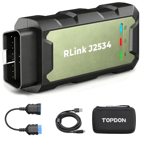
- Advanced VCI Box, Industry-leading J2534 Pass-Thru Technology: This J2534 Pass-Thru Programmer is designed espically for technicians, independent shop owners, and DIY enthusiasts, enables fast, reliable computer-based programming. It supports all J2534 protocols—including the latest DoIP and CAN FD—ensuring full compatibility with both legacy and next-generation vehicles.
- High-Speed OEM-Level Diagnostics & Programming: Unlock true OEM functionality with comprehensive system diagnostics, guided troubleshooting, coding, adaptations, resets, and programming—all designed to slash repair time. This all-in-one tool eliminates the need for multiple OEM devices, boosting efficiency and cutting costs. Equipped with High-Speed USB, it delivers 10x more data per second than competing solutions
- Coverage for 17 Car Brands & Ultra Reliability: Works seamlessly for Chrysler, for Ford(Forscan), for GM, for Nissan, for Toyota, for Honda, for Subaru(SSM4), for Land Rover/Jaguar, for Volvo, for Wuling, for Volkswagen, for Mercedes-Benz, and for BMW. Backed by over 10000 real vehicle tests and benefit from a wealth of practical experience, this OEM reprogramming tool guarantees stable and exceptional performance
- User-Friendly RLink Platform & Expert Support: TOPDON’s proprietary driver management platform offers a clean interface and lifetime free updates. Access a rich library of real-world case studies to stay ahead of the curve. Backed by a support team with 10+ years of J2534 and automotive repair experience, we provide one-on-one assistance to resolve any technical issue.
- 6.6 ft USB-C Cable & Portable Storage Case: The RLink J2534 diagnostic tool features a 6.6ft USB 2.0 Cable and a 1.2 ft OBDII Extension Cable, allows to connection your computer easily outside the vehicle. The included handled carry case offers easy portability, storage, and hanging options—keeping your gear clean and ready to go, anywhere.
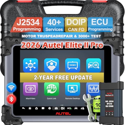
- 【Autel Elite II PRO-Diagnostics at a Smarter Price】As Autel’s latest flagship tool, it matches the core functionality of premium models like the Autel Ultra, MS919, and MS909, the Autel MaxiSYS Elite II PRO is a standout choice: 1)Active Test 2)Auto Scan 2.0-5X faster scanning 3)J2534 Programming & Coding 4)Refresh Hidden Features 5)FCA SGW & D-PDU/RP1210, DOIP CANFD (MS908S PRO II not support) 6)21+Languages 7)40+ Services
- 【J2534 ECU Programming & Coding】Take your vehicle diagnostics to professional heights with the Elite II Pro’s J2534 Reprogramming feature—this cutting-edge scanner delivers OE-level precision for ECU programming and coding, making it a must-have for shops and advanced users. For anyone needing OE-level control over ECU programming and coding, the Elite II Pro’s J2534 functionality is a game-changer.
- 【38+ Reset Services for 150+ Makes】The Autel MaxiSys Elite II Pro isn’t just another scanner—it’s a professional-grade mechanic tool that outperforms even high-end alternatives like Snap-on, such as Crank Relearn, Oil Reset, Brake Bleed, EPB, BMS, Throttle, SAS, Injector Coding, Power Balance Test and etc. It can also perform OE level diagnostics on all available vehicle modules to read & clear DTCs.
- 【Full Bi-Directional Control, 3000+ Active Tests】Unlike basic scanners, the Elite II PRO lets you actively communicate with your vehicle’s onboard systems. Instead of relying on manual vehicle controls, you can send direct commands to ECUs (Engine Control Units) to test subsystem functionality. This means you can verify if components are working properly without guesswork—critical for pinpointing issues quickly.
- 【OE-level All System Scan 2.0】This professional scanner lets you dive deep into all of your vehicle’s systems, providing a comprehensive overview of its health, include: Viewing live data in a 4-in-1 format; freeze data frame, and retrieve ECU info to get a better dive into your car's health; read/ erase 7,000+ DTCs. The Elite II PRO supports multiple VIN detection methods: AutoVIN, manual Scan VIN, and even License Plate lookup. With just one touch, it automatically identifies your vehicle’s VIN data, skipping manual input and giving you instant access to the relevant systems.
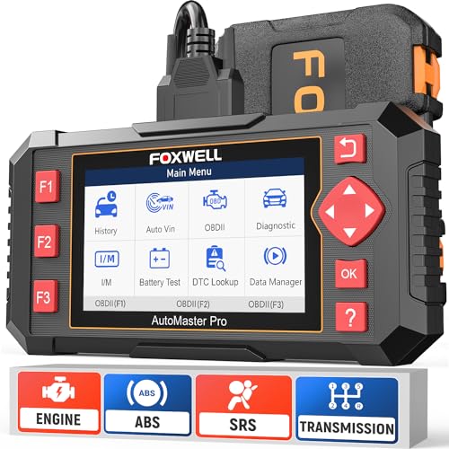
- [Easy to Use—Work Out of the Box] + [FOXWELL 2026 New Version] FOXWELL NT604 Elite scan tool is the 2026 new version from FOXWELL, designed for car owners who want to figure out the cause of issues before fixing car problems by scanning common systems like ABS, SRS, engine, and transmission. The NT604 Elite obd2 scanner diagnostic tool comes with the latest software—no need to waste time downloading software first. Plug the scanner into the OBDII port with OBDII cable to start the diagnosis.
- [Affordable] + [Reliable Car Health Monitor] Will you be confused what happens when the warning light of ABS/SRS/transmission/check engine flashes? Instead of taking your cars to dealership, this FOXWELL scanner will help you do a thorough scanning and detection for your cars and pinpoint the root cause. Note:The device is a diagnostic tool, not a repair tool. To turn off a warning light, you must first physically repair the issue causing it. Only then can the scanner be used to clear the corresponding fault code.
- [5 in 1 Car Diagnostic Scanner] Compared with obd scanners (50-100), NT604 Elite code scanner not only includes their OBDII diagnosis but also serves as ABS/SRS scanner, transmission and check engine code reader. When it’s an odb2 scanner, you can use it to check if your car is ready for annual test through I/M readiness menu. In addition, live data stream, built-in DTC library, data play back and print, all these features are a big plus for it. Note: doesn't support maintenance functions like reset or relearn. For the SRS system, NT604 Elite can read and clear common fault codes not caused by a crash, but crash/collision data cannot be cleared.
- [Fantastic AUTOVIN] + [No extra software fee] Through the AUTOVIN menu, this NT604 Elite car scanner allows you to get your V-IN and vehicle info rapidly, no need to take time to find your V-IN and input one by one. What's more, the NT604 Elite ABS SRS scanner supports 60+ car brands from worldwide (America/Asia/Europe). You don’t need to pay extra software fee. AUTOVIN may not work on some older vehicles or certain vehicle brands. If AUTOVIN fails, please input the vin code manually or go to the Diagnostic Menu to select your vehicle model.
- [Solid protective case KO plastic carrying bag] + [Lifetime update] Almost all same price-level car scanner diagnostic tool only offers plastic bag to hold the scanner.However, NT604 Elite automotive scanner is equipped with solid protective case, preventing your obd2 scanner from damage. Then you don’t need to pay extra money to buy a solid toolbox.

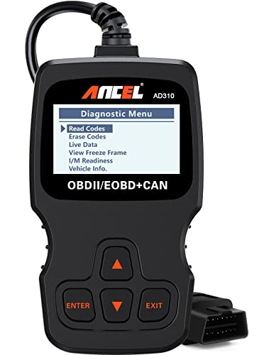
- CEL Doctor: The ANCEL AD310 is one of the best-selling OBD II scanners on the market and is recommended by Scotty Kilmer, a YouTuber and auto mechanic. It can easily determine the cause of the check engine light coming on. After repairing the vehicle's problems, it can quickly read and clear diagnostic trouble codes of emission system, read live data & hard memory data, view freeze frame, I/M monitor readiness and collect vehicle information.
- Sturdy and Compact: Equipped with a 2.5 foot cable made of very thick, flexible insulation. It is important to have a sturdy scanner as it can easily fall to the ground when working in a car. The AD310 OBD2 scanner is a well-constructed mechanic tool with a sleek design. It weighs 12 ounces and measures 8.9 x 6.9 x 1.4 inches. Thanks to its compact design and light weight, transporting the device is not a problem. The buttons are clearly labelled and the screen is large and displays results clearly.
- Accurate Fast and Easy to Use: The AD310 scanner can help you or your mechanic understand if your car is in good condition, provides exceptionally accurate and fast results, reads and clears engine trouble emission codes in seconds after you fixed the problem. This device will let you know immediately and fix the problem right away without any car knowledge. No need for batteries or a charger, get power directly from the OBDII Data Link Connector in your vehicle.
- OBDII Protocols and Car Compatibility: Many cheap scan tools do not really support all OBD2 protocols. AD310 scanner as it can support all OBDII protocols such as KWP2000, J1850 VPW, ISO9141, J1850 PWM and CAN. This device also has extensive vehicle compatibility with 1996 US-based, 2000 EU-based and Asian cars, light trucks, SUVs, as well as newer OBD2 and CAN vehicles both domestic and foreign. Pls confirm with our customer service whether it is compatible with your vehicle before purchasing.
- Home Necessity and Worthy to Own: This is an excellent code reader to travel or home with as it weighs less and it is compact in design. You can easily slide it in your backpack as you head to the garage, or put it on the dashboard, this will be a great fit for you. The AD310 is not only portable, but also accurate and fast in performance. Moreover, it covers various car brands and is suitable for people who just need a code reader to check their car.
SEOCONTENT-START
CUSTOMER INFORMATION: The information in this bulletin is intended for use only by skilled technicians who have the proper tools, equipment, and training to correctly and safely maintain your vehicle. These procedures should not be attempted by “do-it-yourselfers,” and you should not assume this bulletin applies to your vehicle, or that your vehicle has the condition described. To determine whether this information applies, contact an authorized Honda automobile dealer. © 2023 American Honda Motor Co., Inc. – All Rights Reserved Page 1 of 24 Service Bulletin 23-046 June 16, 2023 Version 1 Safety Recall: 2018–23 Odyssey Install FAKRA Service Cables at MOST Bus Network AFFECTED VEHICLES Year Model Trim Level VIN Range 2018–2023 Odyssey ALL except LX Check iN for VIN Eligibility BACKGROUND A coaxial cable terminal was not manufactured to proper specifications. An improperly manufactured terminal may lead to poor communication in the MOST bus network which can potentially affect the quality of audio sound and/or potentially cause the rearview camera to work intermittently or go blank when the vehicle is in the reverse gear. CUSTOMER NOTIFICATION Owners of affected vehicles will be sent a notification of this safety recall. Do an iN VIN status inquiry to verify eligibility. Some vehicles affected by this campaign may be in your new or used vehicle inventory. Failure to repair a vehicle subject to a recall or campaign may subject your dealership to claims or lawsuits from the customer or anyone else harmed as a result of such. To see if a vehicle in inventory is affected by this safety recall, do a VIN status inquiry before selling it. NOTE: ALL VEHICLES AFFECTED on this action must be repaired independent if the vehicle was repaired previously using the following Service Bulletins: • 20-049, 2021 Odyssey: Popping or Crackling from the Speakers; No Sound from the Audio System; Network Loss Message and/or Display Issues • 21-013, Warranty Extension: 2018–20 Odyssey MOST Bus Network Connectors CORRECTIVE ACTION Install the FAKRA splice repair service cables, and splice boxes. Page 2 of 24 PARTS INFORMATION Part Name Part Number Quantity Splice Box 39817-THR-305 7 Splice boxes (14 halves) FAKRA Splice repair service cable (Green) 39165-THR-AB0 3 FAKRA Splice repair service cable (Red) 39165-THR-AA0 3 FAKRA Splice repair service cable (Blue) 39165-THR-AC0 1 TOOL INFORMATION Tool Name Tool Number Quantity Straight FAKRA Puller 07AAC-THRA200 1 Cargo Cap Screw Socket 07AAA-SEPA100 1 Digital Borescope BK5600DUAL55 1 WARRANTY CLAIM INFORMATION Operation Number Description Flat Rate Time Defect Code Symptom Code Template ID Failed Part Number 0101T3 2018–2023 Odyssey: Access the gauge control module, Infotainment Control Unit, in-line connector, and stereo amplifier or tuner- amplifier unit, then replace the affected FAKRA connectors with FAKRA splice repair service cables, and splice boxes. 1.4 hr 6MX00 EEL00 A23046A 39540-THR-A87 Skill Level: Repair Technician Page 3 of 24 FAKRA CONNECTOR HOUSING DISASSEMBLY/FAKRA SPLICE REPAIR SERVICE CABLE ASSEMBLY PROCEDURE 1. Follow the below procedure to gain access to the appropriate listed vehicle components to apply the FALKRA splice repair service cables and splice boxes. 2. The connectors will either be the original FAKRA housing or the WPC FAKRA service housing. NOTE: • There may be multiple components that require the affected FAKRA connectors to be removed. • Use either the straight FAKRA puller or the 90° FAKRA A/B Puller to remove the connector from a component. Original Farka Housing Removal Procedure 1. Use a small screwdriver, remove the secondary lock, then release the tab as shown. 2. Pull to remove the housing form the vehicle harness. Then, discard the housing and lock. WPC FAKRA Service Housing Removal Procedure 1. Release the two locking tabs on the WPC FAKRA Service Housing and remove the housing from the terminal. Page 4 of 24 2. Release the lock tab and remove the terminal from the vehicle harness. FAKRA Splice Repair Service Cable Assembly 1. Install the appropriate FAKRA splice repair service cables and splice boxes as shown in the steps that follow: NOTE: • The splice box arrow must always point in the direction of either the red flag label or red sleeve on the FAKRA splice repair service cable. • If the splice box is installed incorrectly, the repair will fail; MOST ring failure conditions will still occur. 2. Use a small screwdriver to remove the secondary lock and then, release the tab. 3. Pull to remove the housing from the cable and then discard the housing and secondary lock tab from the FAKRA splice repair service cable. Page 5 of 24 4. Connect the appropriate color FAKRA splice repair service cable to the vehicle harness. NOTE: Always disassemble the connectors one at a time to avoid swapping the green and red wires. 5. Attach the splice box halves to the cable connection as shown. 6. When mating the two splice box halves, make sure that all 6 lock tabs are fully engaged. You may hear a click when installing the two halves. NOTE: • The splice box arrow must always point in the direction of the red flag label or red sleeve on the FAKRA splice repair service cable. • If any of the lock tabs break during installation, the splice box halve(s) must be replaced. • If the splice box is installed incorrectly, the repair will fail; MOST ring failure conditions will still occur. 7. Make sure the arrow on the splice box faces towards the tag. Page 6 of 24 8. Once the FAKRA splice repair service cables and splice boxes have been attached to the cable connection, tape the splice boxes and FAKRA service cables to the appropriate component harness. Page 7 of 24 REPAIR PROCEDURE Odyssey – TRIM REMOVAL PROCEDURE 1. Remove side cover. 2. Remove the two screws. 3. Remove the lower vent covers. Page 8 of 24 4. Remove the lower dash panel. 5. Loosen the upper column cover. 6. Disengage the clips around the meter bezel. Then remove the meter bezel and upper column cover as one piece. Page 9 of 24 7. Remove the three screws holding the gauge control module. 8. Remove the driver’s side lower console panel. 9. Remove the driver’s side kick panel. Page 10 of 24 10. Remove the cover above the center display unit. 11. Remove the center dash trim. 12. Remove the passenger side lower panel. Page 11 of 24 13. Remove the passenger lower console panel. 14. Remove the rubber liner and pull back the lower console cover. 15. Remove the dashboard center lower cover and bolt as well as any connectors. Page 12 of 24 16. On the DVD player or center pocket, remove the two upper bolts; loosen the two lower bolts. 17. Remove the DVD player or center pocket to gain access to the two 8 mm bolts holding the Infotainment Control Unit. 18. Remove the screws. Page 13 of 24 19. Remove the two screws from the dashboard center pocket, then pull back the panel. 20. While looking upward from underneath (where the DVD player, CD player, or center pocket was located) loosen the two 8 mm bolts holding the infotainment unit, then remove the unit. 21. In the rear cargo area, remove the rear trim panel. On the right rear quarter panel, remove the hook bolts. If needed, use Cargo Cap Screw Socket (T/N 07AAA-SEPA100) to loosen the bolts. Page 14 of 24 22. Remove the lower passenger sliding door trim. 23. Remove the covers then remove the two screws from the passenger side inner rear quarter panel. NOTE: • Only the driver side rear quarter panel from the service manual is shown below. • All callouts on the service manual image apply to the passenger side rear quarter panel. Page 15 of 24 24. Remove the right quarter inner panel and the connectors. 25. Follow the steps below to install the FAKRA splice repair service cables and splice boxes at each component location. NOTE: See the FAKRA CONNECTOR HOUSING DISASSEMBLY/FAKRA SPLICE REPAIR SERVICE CABLE ASSEMBLY PROCEDURE SECTION above for cable and splice box installation instructions. Page 16 of 24 ODYSSEY – GAUGE CONTROL MODULE REPAIR PROCEDURE 1. Turn the gauge control module to access the rear connectors. 2. Disconnect the FAKRA connectors and any other related connectors at the gauge control module. NOTE: Disassemble the connectors one at a time to avoid swapping the green and red wires. Page 17 of 24 3. Install the matching color FAKRA splice repair service cables and splice boxes. NOTE: • See the above section FAKRA CONNECTOR HOUSING DISASSEMBLY/FAKRA SPLICE REPAIR SERVICE CABLE ASSEMBLY PROCEDURE SECTION for detailed instructions. • The splice box arrow must always point in the direction of the red flag label or red sleeve on the FAKRA splice repair service cable. • If any of the lock tabs break during installation, the splice box halve(s) must be replaced. • If the splice box is installed incorrectly, the repair will fail; MOST Ring failure conditions will still occur. 4. Tape both splice boxes and cables to the gauge control module harness. 5. Reconnect the FAKRA connectors and any other related connectors to the gauge control module. 6. Position the gauge control module into its position but do not install the mounting screws yet. Page 18 of 24 7. Using the digital borescope (T/N BK5600DUAL55) or a commercially available borescope with multiple view angles, inspect the cable routing at the back of the gauge control module as shown below to make sure the cables are routed straight and not sideloaded. Adjust gauge control module harness as needed to achieve proper cable routing. 8. Once you have confirmed the cable routing is correct, install the control module mounting screws. Page 19 of 24 ODYSSEY – INFOTAINMENT CONTROL UNIT REPAIR PROCEDURE 1. Disconnect the red and green FAKRA connectors and any other related connectors at the Infotainment Control Unit. NOTE: Disassemble the connectors one at a time to avoid swapping the green and red wires. 2. Install the matching color FAKRA splice repair service cables and splice boxes. NOTE: • See the above section FAKRA CONNECTOR HOUSING DISASSEMBLY/FAKRA SPLICE REPAIR SERVICE CABLE ASSEMBLY PROCEDURE SECTION for detailed instructions. • The splice box arrow must always point in the direction of the red flag label or red sleeve on the FAKRA splice repair service cable. • If any of the lock tabs break during installation, the splice box halve(s) must be replaced. • If the splice box is installed incorrectly, the repair will fail; MOST Ring failure conditions will still occur. Page 20 of 24 3. Tape both splice boxes and cables to the Infotainment Control Unit Harness. 4. Reconnect the FAKRA connectors and any other related connectors to the Infotainment unit. 5. Position the Infotainment Control Unit into its mounting position. Page 21 of 24 6. Using the digital borescope (T/N BK5600DUAL55) or a commercially available borescope with multiple view angles, inspect the cable routing at the back of the gauge control module as shown below to make sure the cables are routed straight and not sideloaded. Adjust gauge control module harness as needed to achieve proper cable routing. 7. Once you have confirmed the cables routing is correct, install the Infotainment Control Unit mounting screws. Page 22 of 24 ODYSSEY – IN-LINE CONNECTOR REPAIR PROCEDURE 1. Disconnect the blue FAKRA connector at the driver’s kick panel. 2. Install the matching color FAKRA splice repair service cable and splice box. NOTE: • See the above section FAKRA CONNECTOR HOUSING DISASSEMBLY/FAKRA SPLICE REPAIR SERVICE CABLE ASSEMBLY PROCEDURE SECTION for detailed instructions. • The splice box arrow must always point in the direction of the red flag label or red sleeve on the FAKRA splice repair service cable. • If any of the lock tabs break during installation, the splice box halve(s) must be replaced. • If the splice box is installed incorrectly, the repair will fail; MOST Ring failure conditions will still occur. 3. Tape both the splice box and cable to the in-line unit harness. 4. Reconnect the blue in-line FAKRA connector. Page 23 of 24 ODYSSEY – AMPLIFIER/TUNER-AMPLIFIER REPAIR PROCEDURE 1. Disconnect the red and green FAKRA connectors at the amplifier. 2. Install the matching color FAKRA splice repair service cables and splice boxes. NOTE: • See the above section FAKRA CONNECTOR HOUSING DISASSEMBLY/FAKRA SPLICE REPAIR SERVICE CABLE ASSEMBLY PROCEDURE SECTION for detailed instructions. • The splice box arrow must always point in the direction of the red flag label or red sleeve on the FAKRA splice repair service cable. • If any of the lock tabs break during installation, the splice box halve(s) must be replaced. • If the splice box is installed incorrectly, the repair will fail; MOST Ring failure conditions will still occur. 3. Tape both splice boxes and cables to the amplifier, or tuner-amplifier harness. 4. Reconnect the FAKRA connectors and any other related connectors to the amplifier (Elite) or tuner-amplifier (EX, EX-L, Touring). Page 24 of 24 ODYSSEY – REPAIR VERIFICATION PROCEDURE 1. Install all of the removed parts in the reverse order of removal. NOTE: • When reinstalling vehicle components, make sure the harness is routed correctly. A misrouted harness can put pressure on the wires and connectors, causing connection issues. • Do not pull on the components or MOST cables while the FAKRA connectors are connected to help prevent communication issues. 2. Start the vehicle and verify the gauge control module, Infotainment Control Unit operates normal, push the power button OFF, open and close the driver’s door and restart the vehicle. Reverify the gauge control module, Infotainment Control Unit operates normal. If all systems operate normal, repair is complete. 3. If the gauge control module or infotainment unit do not operate as intended after application, reinspect the FAKRA splice repair service cables, splice box connections, and routing. Make sure the splice box arrow is pointing to the red flag label or red sleeve on the FAKRA Splice box service cable. NOTE: If all FAKRA Splice repair service cables, splice box connections and routing are correct follow normal troubleshooting procedures per System Information Search on iN. END
SEOCONTENT-END
This product presentation was made with AAWP plugin.