| “This site contains affiliate links for which OEMDTC may be compensated” |
A12-082
September 17, 2013
Applies To:
2008–12 Accord – ALL
2010–13 Crosstour – ALL
Front Suspension Clunk in Hot Weather
(Supersedes 12-082, dated June 4, 2013, to revise the information marked by the black bars)
REVISION SUMMARY
In Applies To, 2013 Crosstour was added.
SYMPTOM
A clunk is heard in the front suspension while driving over irregular surfaces and in hot weather. The noise goes away temporarily when the vehicle is lifted in the air (the suspension is allowed to hang) and then returned to the ground.
POSSIBLE CAUSE
High ambient temperatures cause the grease to redistribute to the bottom of the ball joint, resulting in a stick-slip knock.
CORRECTIVE ACTION
Replace both of the front lower ball joints with updated service parts made to address this specific symptom. If the ball joints were previously replaced, then replace both front knuckle assemblies.
PARTS INFORMATION
| Accord/ Crosstour Parts Description | Part Number | QTY |
| Lower Ball Joint | 51220-TA0-306 | 2 |
| Ball Joint Cotter Pin | 94201-30220 | 2 |
| Spindle Nut | 90305-S3V-A11 | 2 |
| Tie Rod Cotter Pin | 94201-30220 | 2 |
| Snap Ring
(if knuckle replaced) | 90681-SJK-000 | 1 |
| Upper Arm Ball Joint Cotter Pin (if knuckle replaced) | 94201-20220 | 2 |
| Wheel Bearing
(if knuckle replaced) | 44300-TA0-A61 | 2 |
| Accord Parts Description | Part Number | QTY |
| Knuckle Assembly, Left
(only if prior ball joint replaced) | 51215-TA0-Y60 | 1 |
| Knuckle Assembly, Right
(only if prior ball joint replaced) | 51210-TA0-Y60 | 1 |
| Crosstour Parts Description | Part Number | QTY |
| Knuckle Assembly, Left
(only if prior ball joint replaced) | 51215-TP6-Y00 | 1 |
| Knuckle Assembly, Right
(only if prior ball joint replaced) | 51210-TP6-Y00 | 1 |
| Tool Description | Part Number |
| Adapter G | 07XAF-001050A
07XAF-00105B |
| Ball Joint Remover, 28 mm | 07MAC-SL0A202 |
| Ball Joint Thread Protector
mm | 07AAF-SECA120 |
| Ball Joint Thread Protector
mm | 07AFF-SDAA100 |
| Ball Joint Thread Protector
mm | 07AAE-SJAA100 |
| Ball Joint Tool Kit | 07AAF-TL2A150
(contains the following parts) |
| 07AAF-TL2A100 | |
| 07AAF-TL2A200 | |
| 07AAF-TL2A300A | |
| 07AAF-TL2A300B | |
| 07AAF-TL2A400 | |
| Bearing Driver Attachment | 07746-0010600 |
| C-Frame | OTC7248
(or commercially available) |
| Driver Handle | 07749-0010000 |
| Oil Seal Driver Attachment
mm | 07ZAD-PNAA100 |
| Hub Assembly/
Disassembly Pin, 42 mm | 07GAF-SD4A100 |
| Support Base | 07965-SD90100 |
WARRANTY CLAIM INFORMATION
The normal warranty applies.
*Only one of the following repairs below will apply.
| OP# | Description | FRT |
| 4151A9 | Replace both front knuckles. | 2.3 |
| A | Alignment – add | 0.4 |
| OP# | Description | FRT |
| 4161C0 | Replace both front ball joints. | 1.5 |
| A | Alignment – add | 0.4 |
Failed Part: P/N 51220-TA0-A02
Defect Code: 07409
Symptom Code: 04201
Skill Level: Repair Technician
DIAGNOSIS
Raise the vehicle on a lift high enough to let the suspension hang. Lower the vehicle, then test-drive it to confirm the clunking noise is gone.
- If the noise is gone, go to REPAIR PROCEDURE.
- If the noise is still there, this bulletin does not apply. Continue with normal troubleshooting.
REPAIR PROCEDURE
- Raise and support the vehicle.
NOTE: Do this repair to both sides of the front suspension.
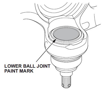
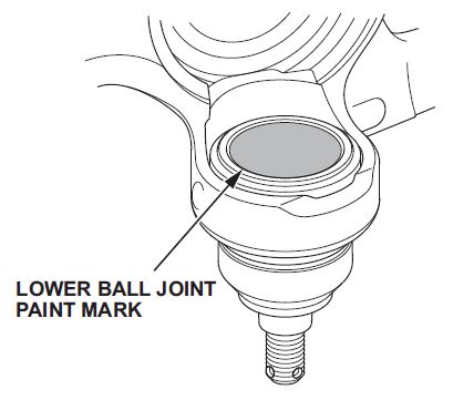
- Clean the top surface of both lower ball joints in the front knuckles and inspect for a paint mark, indicating prior replacement.
- If there is a paint mark, replace both front knuckle assemblies.
NOTE: Ball joints can only be replaced one time on a knuckle and then it requires replacement.
- If there is no paint mark, replace both lower ball joints.
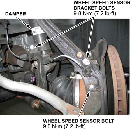
- Remove the wheel speed sensor and its harness brackets at the knuckle assembly and at the damper assembly. Do not disconnect the wheel speed sensor connector.
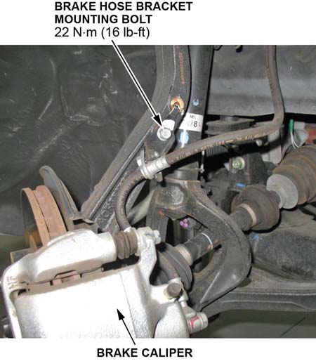
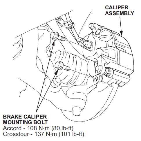
- Remove the brake caliper bracket mounting bolts, then remove the caliper assembly from the knuckle. To prevent damage to the caliper assembly or the brake hose, use a short piece of wire to hang the caliper assembly from the undercarriage. Do not twist the brake hose excessively.
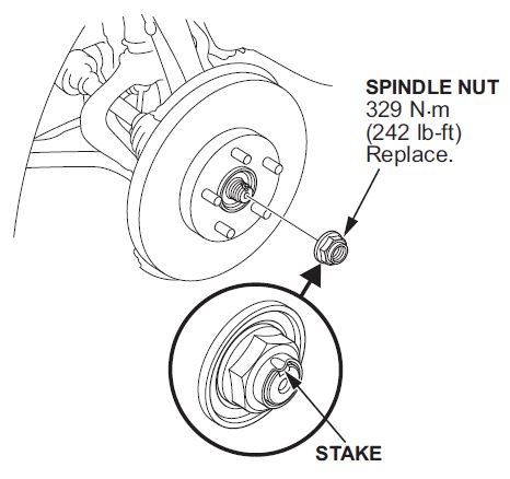
- Pry up the stake on the spindle nut, then remove the nut.
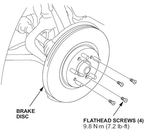
- Remove the front brake disc.
- Remove the brake flathead screws.
- Remove the brake disc from the front hub.
- Check the front hub for damage and cracks.
NOTE: If the brake disc is stuck to the front hub, thread two 8 x 1.25 mm bolts into the brake disc to push it away from the front hub. Turn each bolt 90° at a time to prevent the brake disc from binding.
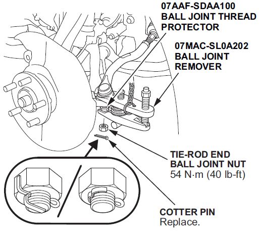
- Remove the cotter pin from the tie-rod end ball joint, then remove the nut.
NOTE: During installation, install a new cotter pin after tightening the nut, and bend its end as shown.
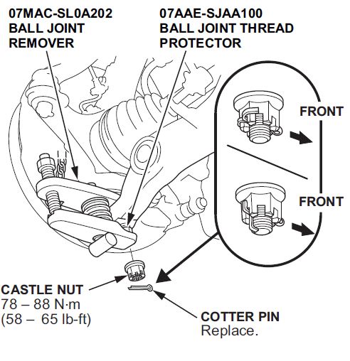
- Disconnect the tie-rod end ball joint from the knuckle using the ball joint thread protector and the ball joint remover.
- Remove the cotter pin from the knuckle ball joint, then remove the castle nut.
NOTE: During reassembly, insert a new cotter pin into the ball joint pin hole from the front to the rear of the vehicle, and bend its end as shown. Check the ball joint pin hole direction before connecting the ball joint.
- Disconnect the knuckle ball joint from the lower arm using the ball joint thread protector and ball joint remover.
NOTE: Do not force or hammer on the lower arm or pry between the lower arm and the knuckle.
- If replacing the knuckle assemblies, go to step 13.
- If using existing knuckle assemblies, go to step 15.
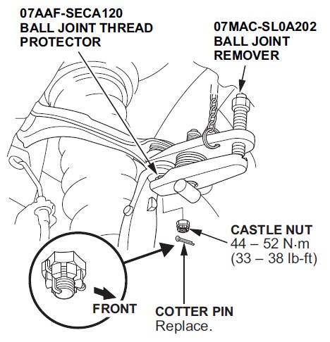
- Remove the cotter pin from the upper arm ball joint, then remove the castle nut.
NOTE: During reassembly, install a new cotter pin into the ball joint pin hole from the front to the rear of the vehicle, and bend its end as shown. Check the ball joint pin hole direction before connecting the ball joint.
- Disconnect the upper arm ball joint from the knuckle using the ball joint thread protector and the ball joint remover.
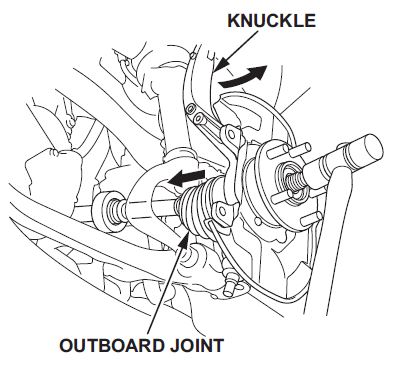
- Pull the knuckle outward and separate the outboard joint from the front hub using a soft face hammer.
NOTE: Do not pull the driveshaft end outward. The driveshaft inboard joint may come apart. During installation, apply grease to the mating surfaces of the wheel bearing and the driveshaft outboard joint.
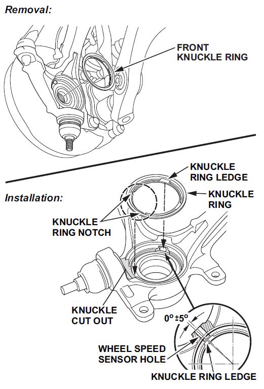
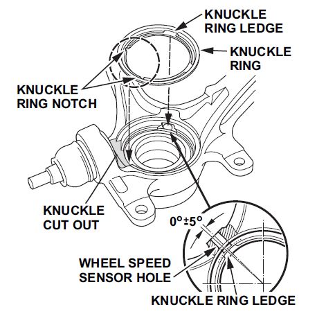
- Remove the front knuckle ring from the knuckle. Inspect it for deformation and damage, and replace it if needed.
NOTE: When installing the front knuckle ring, position the knuckle ring notch portion toward the cutout near the ball joint in the knuckle, and align the center of the knuckle ring ledge portion with the center of the wheel speed sensor hole on the knuckle.
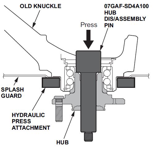
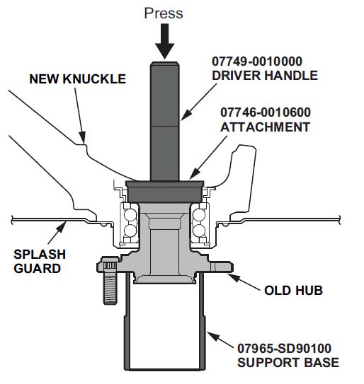
- Separate the hub from the old knuckle using the hub dis/assembly pin and a hydraulic press. Hold the knuckle with the hydraulic press attachment or equivalent tool. Be careful not to damage or deform the splash guard. Hold onto the hub to keep it from falling when pressed clear.
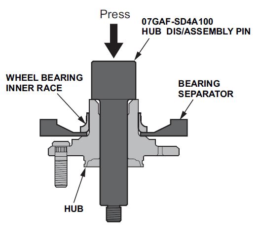
- Press out the wheel bearing inner race of the hub using the hub dis/assembly pin, a commercially available bearing separator, and a hydraulic press.
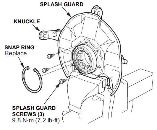
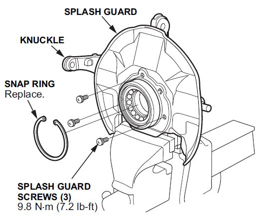
- Remove the snap ring and the splash guard from the knuckle.
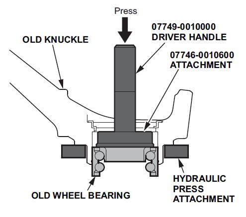
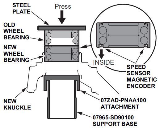
NOTE: This old wheel bearing will be used to assist in the installation of the new wheel bearing into the new knuckle assembly.
- Press a new wheel bearing into the new knuckle using the old bearing, a steel plate, the attachment, the support base, and a press.
NOTE:
- Install the new wheel bearing with the wheel speed sensor magnetic encoder (brown color), toward the inside of the knuckle.
- Remove any oil, grease, dust, metal debris, and other foreign material from the magnetic encoder surface.
- Keep any magnetic tools away from the magnetic encoder surface.
- Be careful not to damage the magnetic encoder surface when you insert the new wheel bearing.
NOTE: Inspect the front knuckle ring for damage or deformation prior to installation, and replace it if necessary.
Position the knuckle ring notch portion toward the cut out near the ball joint in the knuckle, and align the center of the knuckle, and align the center of the knuckle ring ledge portion with the center of the wheel speed sensor hole on the knuckle.
- Install the splash ring and the splash guard.
- Install the splash guard, and tighten the screws to the specified torque, then remove the knuckle assembly from the vise.
- Install the hub onto the new knuckle assembly using the driver handle, the attachment, the support base, and a hydraulic press. Be careful not to damage the splash guard.
- Install the new knuckle assembly, then go tostep 35.
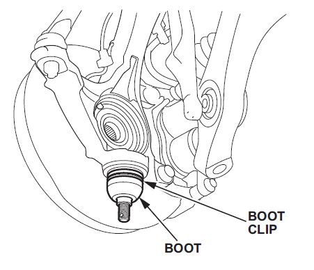
- Remove the boot clip, then remove the boot from the ball joint, and wipe the grease off the exposed portion.
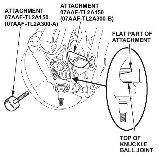
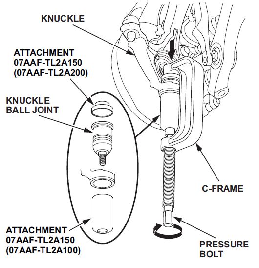
- Clean and wipe off the hub center, then install the attachments (07AAF-TL2A300-A and B) of the ball joint tool kit through the hub center. Position the projection of the attachment (07AAF-TL2A300-B) toward the lower side of the knuckle. Tighten it into place by hand.
NOTE: Make sure that the flat part of the attachment is parallel to the top of the knuckle ball joint.
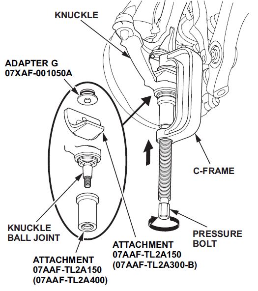
- Position the ball joint tool kit, the adapter G, and the C-frame OTC7248 (commercially available) on to the knuckle ball joint.
NOTE: Make sure the attachments are installed securely.
- Tighten the pressure bolt of the C-frame, and remove the knuckle ball joint.
NOTE: When tightening the pressure bolt, secure the knuckle and the outboard joint.
- Remove the ball joint tool attachments (07AAF-TL2A300-A and B) from the hub.
- Set the new ball joint into the knuckle.
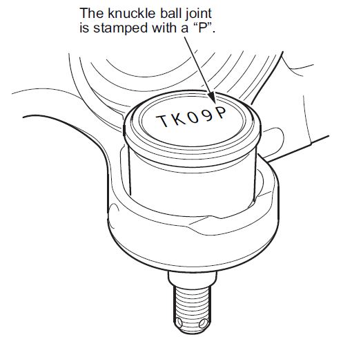
NOTE: Confirm that the new lower ball joint is stamped with a P, indicating a part to resolve clunk noise in high ambient temperature conditions.
- Position the ball joint tool kit and the C-frame OTC7248 (commercially available) to the ball joint. Tighten the pressure bolt of the C-frame until the knuckle ball joint shoulder is fully seated in the knuckle.
NOTE: Make sure the attachments are installed securely. When tightening the pressure bolt, make sure the knuckle and the ball joint are properly aligned.
- Using a yellow oil-based paint marker, paint the top of the knuckle lower ball joint.
NOTE: The paint mark is used to identify a knuckle that has had prior ball joint replacement. Always replace the knuckle as an assembly if the ball joint to be replaced has a paint mark.
- Install the remaining parts in reverse order of removal, and note these items:
- First, install all of the components, and lightly tighten the bolts and the nuts, then raise the suspension to load it with the vehicle’s weight before fully tightening it to the specified torque. Do not place the jack against the ball joint pin of the knuckle.
- Be careful not to damage the ball joint boot when connecting the knuckle.
- Before connecting the ball joint, degrease the threaded section, the tapered portion of the ball joint pin, and the ball joint connecting hole, the threaded section, and the mating surfaces of the castle nut.
- Torque the castle nut to the lower torque specification, then tighten it only far enough to align the slot with the ball joint pin hole. Do not align the castle nut by loosening it.
- Use a new spindle nut on reassembly.
- Before installing the spindle nut, apply a small amount of engine oil to the seating surface of the nut. After tightening, use a drift to stake the spindle nut shoulder against the driveshaft.
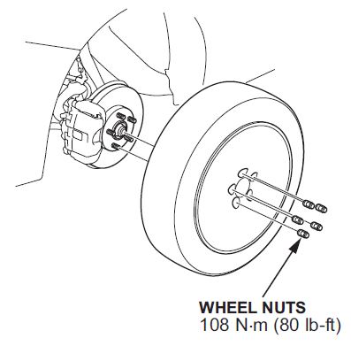
- Before installing the wheels, clean the mating surfaces between the brake disc and the inside of the wheel.
- If the knuckle hub assembly was replaced, before installing the brake disc, clean the mating surfaces between the front hub and the inside of the brake disc.
- Check the wheel alignment, and adjust it if necessary.
 Loading...
- ESSENTIAL TOOL FOR BALL JOINT SERVICE - Use the ORION MOTOR TECH Ball Joint Press Set Ball Joint Tool / Bushing Removal Tool with 4WD Adapter to effortlessly remove press fit parts including ball joints, U-joints, brake anchor pins, and more on most 2-wheel drive (2WD) and 4-wheel drive (4WD) vehicles without removing the control arm from the vehicle.
- PROFESSIONAL GRADE QUALITY AND DURABILITY - Off road weekend warriors, novices, and professional mechanics trust the ORION kit because ORION MOTOR TECH sources the highest quality components from around the world. Constructed from heavy-duty forged steel with black-oxide finish on adapters for maximum strength and longevity that resists rust and corrosion.
- UNIVERSALLY COMPATIBLE WITH A WIDE RANGE OF VEHICLES - Fit most American domestic and imported 2-wheel drive (2WD) and 4-wheel drive (4WD) cars and light pickup trucks that have press-fit type ball joints, include 4-wheel drive (4WD) adapter that allows service for 1967 thru current 1/2 and 3/4 ton 4WD vehicles having the Dana 30 or 44 front axle (found on Ford, GM, Dodge, IHC and Jeep vehicles).
- CONVENIENTLY ORGANIZED IN CUSTOM MOLDED CASE - Ball joint press / bushing/ removal tool kit is enclosed inside a heavy-duty 11” x 3” x 15” inch (27.9cm x 7.6cm x 38.1cm) plastic blow-molded carrying case with handle for easy storage, safe storage, and quick organization. Package include: 3x Receiving Tube, 1x Removal Adapter, 1x Installation Adapter, 1x Screw, 1x Install Cup Adapter, 1x Forcing-screw Press, 1x Receiving Cup, 1x Installing Cup.
- ORION MOTOR TECH - We pursue outstanding quality and professional technical support. If you are not satisfied with this product or if you have any question, please feel free to let us know.
- ALL IN ONE FRONT END SERVICE KIT: Containing 5 adjustable tools for a wide range of domestic and import vehicles. Comes with 1x Ball Joint Separator, 1x Tie Rod and Ball Joint Remover, 1x Conical Pitman Arm Puller, 1x Pitman Arm and Tie Rod End Puller, 1x Pitman Arm Puller, 1x well-organized ABS case
- HARDENED ALLOY CONSTRUCTION: Extraordinarily tough and durable alloy means these tools can stand up to the toughest jobs. This front end service tool kit can remove the most stubborn ball joints, tie rod ends, and pitman arms
- UNIVERSALLY COMPATIBLE WITH A WIDE RANGE OF VEHICLES: The versatile design allows this tool to be used as a pitman arm remover, ball joint separator, or tie rod end puller for many small, domestic rear-wheel-drive vehicles, import vehicles, and light trucks
- PROFESSIONAL PORTABLE ABS CASE: The custom-molded case is crafted from high-quality ABS hard plastic for the amateur or professional mechanic on the go. Conveniently keeps all your tools in one organized and secure place. Never miss out on a job or project from a misplaced tool
- WIDELY APPLICATION: Professional ball joint & u-joint service kit, works for ball joint removal/installation, U joint removal/installation and brake anchor pins assemble/disassemble. Even remove rusted and corroded parts.
- UNIVERSAL COMPATIBLE: Fits most American domestic and imported 2-wheel drive (2WD) and 4-wheel drive (4WD) cars, vehicles and light pickup trucks that have press-fit type ball joints.
- EASY OPERATION: Includes heavy-duty C frame press, receiver tubes, and installation and removing adapters. Ideal for removal and installation of press-fit parts such as ball joints, universal joint and truck brake anchor pins without removing the control arm from the vehicle, effectively avoid the deformation of the front axle and the ball joint.
- PREMIUM MATERIAL: Heavy duty C-clamp with forcing screw constructed from heavy-duty forged 20# steel, ensure maximum strength and toughness; Black-oxide finished adapters for anti-rust and anti-corrosion, extend service life.
- HEAVY DUTY CARRYING CASE: Come with a 15.35 x 12 x 3.34inch heavy-duty plastic blow molded carrying case with handle for simple organization, dry storage and safe transport.
- Heavy-Duty Applications: It is a heavy-duty press tool for Ball Joint that can withstand the most challenging tasks, ensuring durability and long-lasting performance. perfect for frequent users who need a sturdy and durable tool, It's an ideal tool for various vehicles, excellent for removal and installation of press-fit parts such as ball joints, U joint, Control arm bushing and brake anchor pins for Most 2WD and 4WD Cars and Light Trucks. Hardend C Clamp Puller can excellent press rusted parts effortlessly.
- Complete with Adapters: Our hd ball joint installation tool with 4 wheel drive adapters, making it compatible with a broad range of four wheeler vehicle models. It gives you the flexibility and convenience needed to get the job done right. Fit most American domestic and imported car SUV ATV UTV pickup and light truck and Fit on Ford, GM, Dodge Ram, IHC and Jeep vehicles.
- Robust Construction: Crafted with high-grade materials, this ball joint press kit promises heavy-duty performance, enabling you to tackle even the most stubborn ball joints and bushings. Upper and Lower Control Arm Ball Joint Removal Tool be able to: Remove Upper/Lower Ball Joints, Install Upper/Lower Ball Joints, Remove/Install Brake Anchor Pin, Disassemble/Assemble Universal U Joints.
- Package include: 3x Receiving Tube, 1x Removal Adapter, 1x Installation Adapter, 1x Screw, 1x Install Cup Adapter, 1x Forcing-screw Press, 1x Receiving Cup, 1x Installing Cup.
- 4 in 1 ball joint service kit tool set Four Wheel Drive Is Made of Strong Carbon Steel, Instruction In English Included ,Plastic Carrying Red Case Package.
- Gearwrench's Ball Joint Separator is made for separating the ball joint from the spindle support arm on domestic and import front wheel drive vehicles
- Adjustable for different size ball joints
- Suitable for most cars and light trucks (not intended for use on 3/4 ton or 1 ton trucks)
- Works on ball joints from 1-1/8” to 2-1/8” and 30 to 56mm in size
- Slot is 7/8" wide by 1-1/4" Deep
- Pickle Fork Separator Tool: The tapered fork wedge design of this ball joint separator tool focuses on the fundamentals of machine technology for an easy and uncomplicated process
- Precision Performance: Striking the handle with a hammer separates the ball joint cleanly; Designed with a 15/16 inch opening for a firm hold and secure removal
- Hardened Steel: The heat treated steel alloy construction of this ball joint separator stands up to tough jobs; Zinc plating resists rust and extends service life
- Thoughtful Design: Ball joint separator handle features a nonslip knurled texture; Used as designed, this front end service tool will stand up to years of use
- Versatile Uses: This universal ball joint separator can be used for a variety of repairs; For example, the ball joint tool can also be used on CV drive shafts
- ESSENTIAL TOOL FOR BALL JOINT SERVICE - Use the ORION MOTOR TECH 21PCS Ball Joint Press Set Ball Joint Tool / Bushing Removal Tool with multi-size adapter to effortlessly remove press fit parts including ball joints, U-joints, brake anchor pins, and more on most 2-wheel drive (2WD) and 4-wheel drive (4WD) vehicles without removing the control arm from the vehicle.
- UNIVERSALLY COMPATIBLE WITH A WIDE RANGE OF VEHICLES - Use the ORION MOTOR TECH Ball Joint Press Set Ball Joint Tool / Bushing Removal Tool with all the receiver tubes and removing/installing adapters needed to effortlessly remove press fit parts including ball joints, U-joints, brake anchor pins, and more on most GM, Chevy, Ford, and Dodge 2 and 4 wheel drive pickups, vans and sport utility vehicles, will service perfect for vehicles having the Dana 28, 30, 35, 44, 60 axle
- PROFESSIONAL GRADE QUALITY AND DURABILITY - Off road weekend warriors, novices, and professional mechanics trust the ORION kit because ORION MOTOR TECH sources the highest quality components from around the world. Constructed from heavy-duty forged solid carbon steel with anti-rust black-oxide finish on adapters for maximum strength and longevity that resists rust and corrosion.
- CONVENIENTLY ORGANIZED IN CUSTOM MOLDED CASE - Ball joint press / bushing/ removal tool kit is enclosed inside a heavy-duty ABS plastic blow-molded carrying case with handle for easy storage, safe storage, and quick organization. Package include: 9x Adapters, 1x Center Rod, 1x C-Frame, 1x Install Adapter, 1x Install Cup, 1x Install Cup Adapter, 1x Receiving Cup, 3x Receiving Tube, 1x Removal Adapter, 1x Screw, 1x Sleeve.
- ORION MOTOR TECH - We pursue outstanding quality and professional technical support. If you are not satisfied with this product or if you have any question, please feel free to let us know.
- Handle Ball Joints with Ease: Orion Motor Tech's 23pc ball joint removal tool kit lets you quickly and easily remove and install stubborn press-fit parts, including ball joints, U joints, and brake anchor pins.
- Easily Repair Your Chryslers: Our specially designed 4-point sockets (1-59/64 in. & 2-9/64 in.) are tailored to fit numerous Chrysler vehicles, ensuring a secure and accurate fit when removing and installing their uniquely threaded upper ball joints.
- Gentle on Your Vehicle: Our 9 inch C-frame press with a 6 inch opening and an extra-long jackscrew provides even and straight force to let you smoothly press out joints without damaging other components.
- Universal Compatibility: Our ball joint tool kit works with most 2WD and FWD vehicles, including GM, Chrysler, Ford, Jeep, Dodge, and more, thanks to its versatile receiving tubes and adapters.
- Engineered for Durability: Our ball joint press kit is crafted from premium AISI 1045 carbon steel, carefully forged and blackened to ensure superior strength and excellent corrosion resistance.
- Universal Compatibility: The ball joint removal tool is designed for domestic and imported 2WD/4WD cars and light trucks with press-fit ball joints. Includes a 4WD adapter for 1/2 and 3/4 ton 4WD vehicles with the Dana 30 or 44 front axle on Ford, GM, Dodge, IHC, and Jeep vehicles.
- Easy Operation: The PUNMEW ball joint press simplifies vehicle part removal and installation. Easily remove lock ring retainers from brake anchor pins, then apply the C-frame press to the brake spider. Tighten the forcing screws to effortlessly remove mounting pins, making your repair tasks a breeze.
- Package Includes: 3x Receiving Tubes, 1x Removal Adapter, 1x Installation Adapter, 1x Screw, 1x Install Cup Adapter, 1x Forcing-screw Press, 1x Receiving Cup, 1x Installing Cup.
- Robust and Functional: PUNMEW' ball joint removal tool kit features heavy forged steel with black-oxide finish, ensuring durability. Four-wheel drive adapters simplify press-fit part removal, enhancing work efficiency for enthusiasts and professionals alike.
- Organized and Portable: This ball joint press is conveniently stored in a custom case with handle, featuring essential components for efficient repairs.
- EASY TO USE: This tie rod removal tool separates ball joints without damaging other components, designed specifically for quick and easy separation of a vehicle’s ball joint from the spindle support arm.
- ADJUSTABLE: 2-Stage height adjustment feature uses a heat-treated steel pin thrust bolt and steel ball insert, allowing quick and easy height adjustment changes.
- WIDE APPLICATION: This ball joint separator tool is adjustable for different size ball joints, it can be used on most press-fit ball joint applications. Max. opening range is 1/2 inch & 1-7/8 inch.
- PREMIUM MATERIAL: This ball joint press kit is made of high hardness carbon steel, heat-treated, sturdy and steady, corrosion resistant, wear resistant, with reliable use and long service life.
- AFTER-SALES DESCRIPTION:If you have any questions about the purchased tool, please contact us in time, and your problems will be solved in time.
Last update on 2025-05-08 / Affiliate links / Images from Amazon Product Advertising API
This product presentation was made with AAWP plugin.
