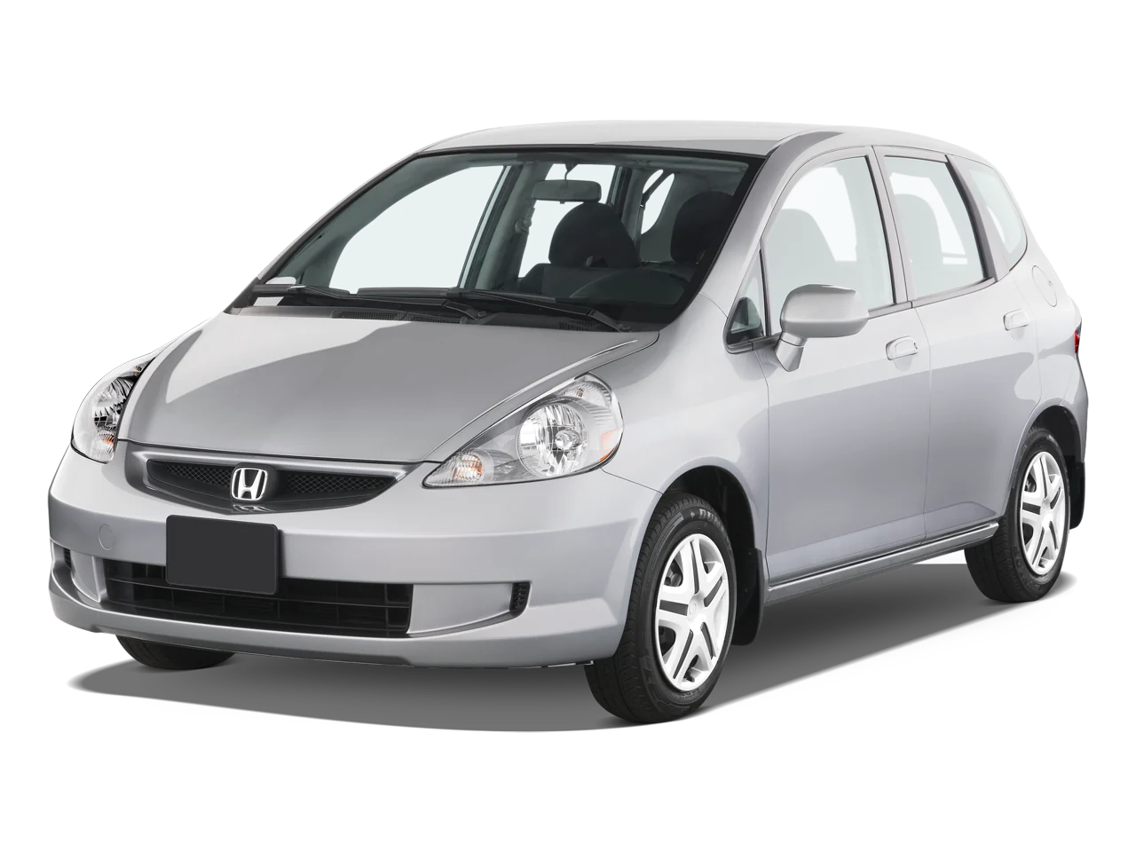
A21-042
June 8, 2021
Version 2
AFFECTED VEHICLES
| Year | Model | Trim Level | VIN Range |
| 2007-08 | Fit (A/T models only) | ALL | Check the iN VIN status for eligibility. |
BACKGROUND
Due to improper manufacturing, the paint on the driveshaft near the dynamic damper may peel and chip over time, exposing the bare metal and potentially causing it to corrode under the dynamic damper. A corroded driveshaft may break during high torque conditions, rendering the vehicle without propulsion, or allowing the vehicle to roll while in Park, which can increase the potential of a crash or injury.
This recall applies only to vehicles with driveshafts that have a dynamic damper. If only one driveshaft has a dynamic damper, do the INSPECTION PROCEDURE on that driveshaft only, and replace only that driveshaft if it fails the inspection.
The affected VIN population for this recall was determined based on information available to Honda at the time the recall was announced. If a customer believes their vehicle should be included in the campaign due to information not available to
Honda (either at the time of recall announcement or thereafter), contact your DPSM and have the customer contact American Honda with their concern. For any questions or concerns that customers may have, you may direct them to contact American Honda’s Customer Support & Campaign Center at 888-234-2138.
CUSTOMER NOTIFICATION
Owners of affected vehicles will be sent a notification of this campaign.
Do an iN VIN status inquiry to make sure the vehicle is shown as eligible.
Some vehicles affected by this campaign may be in your new or used vehicle inventory.
Failure to repair a vehicle subject to a recall or campaign may subject your dealership to claims or lawsuits from the customer or anyone else harmed as a result of such failure. Before selling a vehicle in inventory, always check if it is affected by a safety recall by conducting a VIN status inquiry.
CORRECTIVE ACTION
This recall applies only to vehicles with driveshafts that have a dynamic damper. If neither driveshaft has a dynamic damper, this recall does not apply. If only one driveshaft has a dynamic damper, do the INSPECTION PROCEDURE on that driveshaft only, and replace only that driveshaft if it fails the inspection.
This recall applies only to vehicles with driveshafts that have a dynamic damper. If only one driveshaft has a dynamic damper, do the INSPECTION PROCEDURE on that driveshaft only, and replace only that driveshaft if it fails the inspection.
If either driveshaft fails inspection and parts are not available, the vehicle must not be returned to the customer until replacement driveshafts are installed. If the customer needs alternative transportation due to parts shortages, contact your DPSM and make arrangements for the customer.
Failure to follow the inspection and repair procedure correctly may result in the driveshaft breaking under the dynamic damper. This could render the vehicle without propulsion, or allow the vehicle to roll while in Park. Improper repairs could be subject to debit.
PARTS INFORMATION
| Part Name | Part Number | Quantity |
| Right Driveshaft Assembly Kit (includes right side driveshaft assembly, axle nut, castle nut, and set ring for half-shaft). | 06440-SLN-305 | 1 |
| (Left Driveshaft Assembly Kit (includes left side driveshaft assembly, axle nut, castle nut). | 06440-SLN-306 | 1 |
REQUIRED MATERIALS
| Part Name | Part Number | Quantity |
| ATF-DW1 (1 bottle will repair 5 vehicles) (A/T only) | 08200-9008 | 1 |
| M-77 Assembly Paste (1 tube will repair 12 vehicles) | 08798-9010 | 1 |
TOOL INFORMATION
NOTE:
- The tools listed below are required tools that should be in your dealer inventory. Order additional tools only if your tools are damaged and need replacement.
- For the 28 mm Ball Joint Remover, part numbers 07MAC-SL00200, 07MAC-SL00201, or 07MAC-SL0A202 can be used in place of 07MAC-SL00202.
| Tool Name | Part Number | Quantity |
| 28 mm Ball Joint Remover | 07MAC-SL00202 | 1 |
| 12 mm Ball Joint Thread Protector | 07AAF-SDAA100 | 1 |
INSPECTION PROCEDURE
NOTE: This recall applies only to vehicles with driveshafts that have a dynamic damper. If neither driveshaft has a dynamic damper, this recall does not apply. If only one driveshaft has a dynamic damper, do the INSPECTION PROCEDURE on that driveshaft only, and replace only that driveshaft if it fails the inspection.
- Raise and support the vehicle.
- Use a clean shop towel to wipe any excess dirt and debris from the driveshafts between the outer joint and the dynamic damper.
NOTE: Paint chips may be sharp and could cut bare hands. Use gloves when wiping the driveshaft.
- Using a ruler and yellow paint marker, measure 40 mm (1-11/16 in) away from the dynamic damper, and mark the driveshaft with a dot. Click HERE to view a video on how to do the inspection procedure.
NOTE: Do not scribe or damage the painted surface of the driveshaft. Any replaced driveshafts may be called in for inspection.
- Rotate the axle 1/4 turn and repeat the step above three times until there are four paint dots on the axle.
- Connect the four painted dots around the axle using masking tape.
- Using the masking tape as a guide, trace a line all around the axle using the yellow paint marker. Marking the line accurately is important, especially if there is damage close to or inside the 40 mm line.
- Remove the masking tape.
- Inspect the driveshaft surface between the dynamic damper and the line for peeling paint, cracks, or blisters. Corrosion or paint defects between the outer joint and the yellow line are OK.
Is there peeling paint, cracks, or blisters on either driveshaft within 40 mm (1-11/16 in) of the dynamic damper?
Yes – Go to REPAIR PROCEDURE.
No – The driveshafts are OK. Return the vehicle to the customer.
REPAIR PROCEDURE
NOTE: Replace only the affected driveshaft(s) as determined after doing the INSPECTION PROCEDURE.
- Remove the front wheel of the driveshaft you are replacing.
- Pry up the stake on the spindle nut, then remove it.
- Remove the lock pin from the lower arm ball joint, then remove the castle nut.
- Separate the ball joint from the knuckle using the Ball Joint Thread Protector (T/N: 07AAF-SDAA100) and Ball Joint Remover (T/N: 07MAC-SL0A202). Grease the threads and tip of the pressure bolt on the ball joint remover, and make sure the pivot bolt is not parallel to the ball joint remover arms. For additional information on how to use the tools, refer to the service information.
NOTE:
- To avoid damaging the ball joint, install the ball joint thread protector onto the threads of the ball joint.
- Be careful not to damage the ball joint boot when installing the remover.
- Do not force or hammer on the lower arm, or pry between the lower arm and the knuckle to prevent damage.
- Use a soft-face hammer to separate the outboard joint from the front hub.
- Pull the knuckle outward to separate the outboard joint from the front wheel hub.
- Driver’s side driveshaft only: Use a pry bar to pry the inboard joint from the transmission housing. Then, remove the driveshaft as an assembly.
NOTE:
- Do not pull on the driveshaft, or the inboard joint may come apart.
- Pull the inboard joint straight out to avoid damaging the oil seal.
- Be careful not to damage the transmission oil seal with the pry bar.
- Passenger’s side driveshaft only: Using a punch and hammer, drive the inboard joint off of the intermediate shaft. Then, remove the driveshaft as an assembly.
NOTE:
- Do not pull the assembly by the driveshaft, the inboard joint may come apart.
- Be careful not to damage the transmission oil seal with the pry bar.
- Driver’s side driveshaft only: Replace the set ring on the inboard joint.
- Passenger’s side driveshaft only: Replace the set ring on the intermediate shaft.
- Make sure the connecting surfaces of the joint and splined section are clean any debris or rust particles using a shop towel and/or compressed air before starting installation.
- Apply about 5 g (18 oz) of M-77 Assembly Paste (P/N 08798-9010) to the contact area of the outboard joint and front wheel bearing.
- Insert the inboard end of the driveshaft into the differential or intermediate shaft until the set ring locks in the groove. Make sure to insert the driveshaft(s) straight in to avoid damaging the oil seal.
NOTE: You do not need to apply any grease to the new driveshaft(s), as they come pre-greased.
- Install the outboard joint into the front hub on the knuckle.
- Wipe off any grease contamination from the tapered ball joint section and threads, then install the knuckle onto the lower arm. Make sure not to damage the ball joint boot.
- Install the new castle nut, and torque it to the lower torque specification. Then, tighten it until the slot on the castle nut aligns with the ball joint pin hole. Install the lock pin into the pin hole as shown.
NOTE: Do not loosen the castle nut to align the castle nut slot and ball joint pin hole.
- Apply a small amount of engine oil to the seating surface of the new spindle nut. Then, install and torque the spindle nut. After torqueing it, use a drift punch to stake the spindle nut shoulder against the driveshaft.
NOTE: If you are going to use an air or battery powered impact gun to install the nut, make sure to turn down the air or power so you do not overtighten it, then torque it to specification using a torque wrench.
NOTE: It is important to know that many air and battery powered impact guns can achieve 2 or 3 times the axle nuts torque specification. If you severely over-torque an axle nut, it is possible to break a driveshaft as shown below:
- Clean the mating surfaces of the brake disc and front wheel, then install the front wheels.
- Turn the front wheel by hand, and make sure there is no interference between the driveshaft and surrounding components.
- Top off the transmission fluid as needed. Do not fill above the upper mark on the dipstick, and always use ATF-DW1 (P/N 08200-9008).
- Check the wheel alignment and adjust it if necessary.
END
Safety Recall – Drive Shaft May Corrode and Fail – 2007-2013 Honda Fit & 2012 Civic Hybrid
Safety Recall: 2007-2008 Honda Fit Driveshaft Inspection
Remedy Instructions and TSB
June 8, 2021
Version 2
RCRIT-20V770-6181.pdf 1694.125KB
Remedy Instructions and TSB
April 2, 2021
Version 1
RCRIT-20V770-9642.pdf 1644.268KB
Latest Recalls Documents

- 100% Brand New item,High Quality Tools,Has a nice Black oxide finish.
- Nut size:2 1/4",Fits 1/2 Rachet/Breaker bar.
- Compatible With: 2007 - Present/now For Harley Twin Cams/2006 -Present/now For Harley for Dyna
- The tool has a Threaded Bushing and can be used with a 1/2" drive ratchet or breaker bar.
- This tool is a Main Shaft Sprocket Wrench Tool for the 2 1/4" Nutl ,comes with a threaded bushing.his kit fits for all Harley Davidson front transmission pulley 2-1/4"
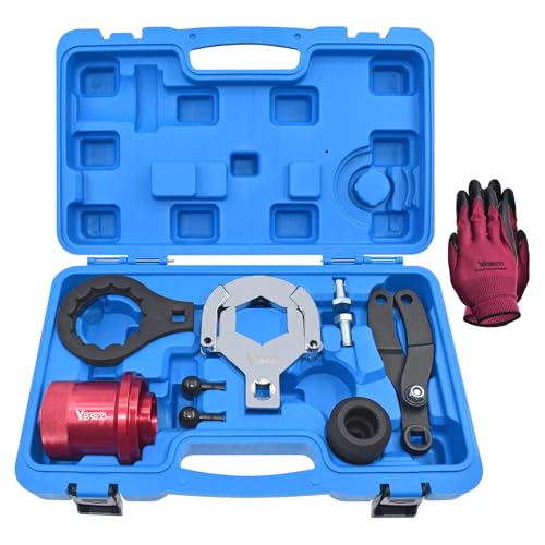
- Yuesstloo rear axle installer remover kit is used to install and remove the screw nut between the rear drive shaft and the differential. Also can be used to replace the differential shaft seal.
- Compatible with BMW E70 E90 E91 E92 X3 X5 X6 RWD 4WD. OEM Equivalent Part Number: 335040, 335050, 335060, 335080, 230020.
- Made of high quality steel, with high hardness, not easy to break and deform.
- Convenient to transport and store. Comes with a carrying case, all parts are neatly placed. And we prepare a pair of gloves for you to use when using the tool.
- If there is some problem with our products, you can get help from us. Customer satisfaction is our top priority.
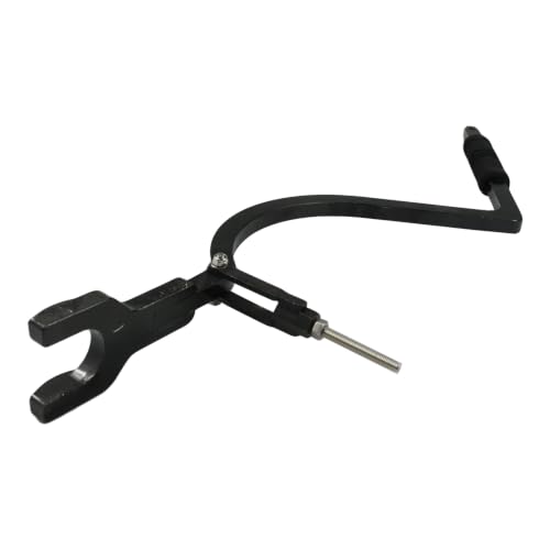
- 【Part Numbers】Compatible With 529036026 Drive Shaft Carbon Seal Tool. Designed To Help Remove The Drive Shaft C-Clip, Floating Ring And Carbon Seal Retaining Ring On Compatible Sea-Doo Models
- 【Application】Drive Shaft C-Clip Remover Tool Compatible With Sea-Doo GTI, GTR, GTS, GTX, RXP, RXT, Wake And Fish Pro Models With 1503 Engines, Including GTI 130, GTI SE 130, GTI SE 155, GTR 215, GTS 130, GTX 155, GTX 215 And Related Models. Compatible With Sea-Doo RXP 155, RXP 215, RXP-X 255, RXP-X 260, RXT 215, RXT 260, RXT-X 255, RXT-X 260, Wake 155, Wake 215, Fish Pro 155 And Related 4-TEC Models. Please Check The Full Fitment Before Purchase
- 【Specification】Made Of 40Cr Steel With CNC Machined Construction For Accurate Fit And Stable Use. The Adjustable Threaded Rod Helps Fit Different Engine Compartments And Provides Leverage To Push Back The Metal Hat For C-Clip Removal
- 【Package Includes】1 × Drive Shaft C-Clip Remover Tool. Designed To Make Carbon Seal, Floating Ring And Drive Shaft Service More Convenient On Compatible Models
- 【Notice】This Is A Replacement Tool, Not An Original Tool. Please Carefully Check Your Original Tool Number, Vehicle Model, Year, Engine Type, Working Space And Product Pictures Before Purchase To Make Sure This Tool Fits Your Repair Needs
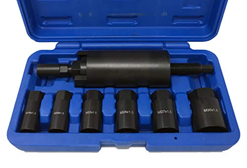
- This Drive Shaft Puller kit is designed for pulling drive shafts into hubs
- Kit comes with six different size adapters: M16 x 1. 5 (Subaru), M20 x 1. 5 (VW/Audi/Porsche), M22 x 1. 5 (BMW E30), M24 x 1. 5 (BMW E36 & Mercedes Benz W203), M27 x 1. 5 (BMW E32/E34/E38/E39/E53) and M30 x 1. 5 (BMW E32/E36/E34)
- Applications: BMW, VW, Audi, Porsche, Mercedes Benz & Subaru
- Visit ctatools for application details
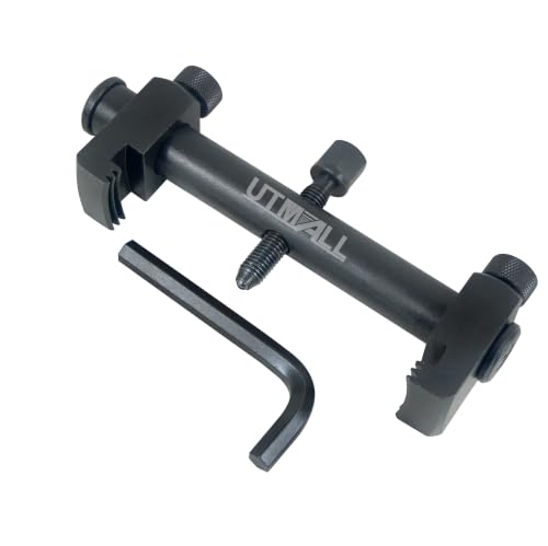
- Designed for removal of stubborn or seized ribbed crankshaft and auxiliary pulleys.
- Suitable for use on crankshafts, alternators, air conditions unit, and Water pumps
- Allows removal without the risk of damaging the pulley in restricted engine bays.Low profile arms allow use in restricted engine bays.
- Max opening jaws 6.3" (165mm), Close: 1-1/4" (35mm)
- We provide 12-month warranty service. If the tools have quality problems, please contact us and apply for replacement and return to ensure the shopping experience.
SEOCONTENT-START
Service Bulletin 21-042 June 8, 2021 Version 2 Safety Recall: 2007-08 Fit Driveshaft Inspection Supersedes 21-042, dated April 2, 2021, to revise the information highlighted in yellow REVISION SUMMARY Under REPAIR PROCEDURE step 17, a note and images were added. WARRANTY CLAIM INFORMATION NOTE: If the vehicle has no driveshafts with a dynamic damper, no further action is needed. Please submit a warranty claim for Inspection ONLY, to close out the campaign. Operation Number Description Flat Rate Time Defect Code Symptom Code Template ID Failed Part Number 2195B3 Inspect both driveshaft assemblies only. 0.3 hr 6DY00 PAV00 A21042A 44306-SLN-L00 2191CB Replace both driveshaft assemblies (includes inspection, fluid check, and wheel alignment). 1.9 hr 6DY00 PAV00 A21042B 44306-SLN-L00 2191CC Replace left driveshaft assembly only (includes inspection, fluid check, and wheel alignment). 1.5 hr 6DY00 PAV00 A21042C 44306-SLN-L00 2191CD Replace right driveshaft assembly only (includes inspection, and wheel alignment). 1.1 hr 6DY00 PAV00 A21042D 44305-SLN-L00 Skill Level: Repair Technician
**************************************************************************************************************
SEOCONTENT-END
This product presentation was made with AAWP plugin.