
| “This site contains affiliate links for which OEMDTC may be compensated” |
April 12, 2019
Loose Battery Terminal Connections
A damaged parking rod can allow the vehicle to roll when parked, increasing the risk of a crash or injury.
NHTSA Campaign Number: 19V299
Manufacturer Honda (American Honda Motor Co.)
Components POWER TRAIN, ELECTRICAL SYSTEM
Potential Number of Units Affected 50,504
Summary
Honda (American Honda Motor Co.) is recalling certain 2018-2019 Odyssey vehicles. Loose battery terminal connections or a degraded battery may cause the Transmission Control Unit (TCU) to unexpectedly reboot. Upon rebooting, the TCU may shift the transmission to the “Park” position, possibly damaging the parking rod.
Remedy
Honda will notify owners, and dealers will ensure the battery terminal connections are secure and will update the TCU software, free of charge. Additionally, the parking rod effectiveness will be checked. The recall began May 31, 2019. Owners may contact Honda customer service at 1-888-234-2138. Honda’s numbers for this recall are Z4J, Y4K.
Notes
Owners may also contact the National Highway Traffic Safety Administration Vehicle Safety Hotline at 1-888-327-4236 (TTY 1-800-424-9153), or go to www.safercar.gov.
Check if your Honda has a Recall
Service Bulletin
A19-043
April 12, 2019
Version 1
Safety Recall: 2018-19 Odyssey Battery Terminal Inspection and Transmission Replacement
AFFECTED VEHICLES
| Year | Model | Trim | VIN Range |
| 2018-19 | Odyssey | Touring, Touring-Elite | Check the iN VIN status for eligibility. |
BACKGROUND
A momentary voltage loss to the TCM, usually caused by a loose battery terminal, can cause the transmission to shift to Park while driving. When this happens, the parking mechanism could get damaged, and the vehicle may move while the shifter is in Park.
Honda has developed software to correct this issue. See S/B 19-046. This service bulletin provides information to replace the transmission of vehicles that were identified as having their transmission shift to Park while driving . The new transmissions come with the new software.
CUSTOMER NOTIFICATION
Owners of affected vehicles will be sent a notification of this campaign.
Do an iN VIN status inquiry to make sure the vehicle is shown as eligible.
Some vehicles affected by this campaign may be in your new or used vehicle inventory.
Failure to repair a vehicle subject to a recall or campaign may subject your dealership to claims or lawsuits from the customer or anyone else harmed as a result of such failure. To see if a vehicle in inventory is affected by this safety recall, do a VIN status inquiry before selling it.
CORRECTIVE ACTION
- Replace the transmission (the new transmission comes with the new software).
- Inspect the battery terminals.
- Clean or replace the battery terminals and/or battery if the terminal inspection fails (an extremely small percentage of vehicles may require a new battery or battery terminals).
PARTS INFORMATION
| Part Name | Part Number | Quantity |
| Reman A/T Kit (2019 models) | 06200-5MX-A83RM | 1 |
| Reman A/T Kit (2018 models) | 06200-5MX-A77RM | 1 |
| Flange Bolt (12 x 120) | 90051-5J4-000 | 1 |
| Flange Bolt (12 x 45) | 90165-SDA-A00 | 2 |
| Flange Bolt (12 x 85) | 95701-12085-07 | 1 |
| Flange Nut (12 mm) | 90371-SAA-010 |
4 |
| Flange Bolt (10 x 35) | 90163-SDA-A01 | 2 |
| Flange Bolt (10 x 103) | 90163-SJH-000 | 1 |
| Flange Bolt (10 x 25) | 90167-SAA-010 | 4 |
| Self-Lock Nut (10 mm) | 90212-SA5-003 |
9 |
| Pre Chamber Gasket | 18393-SDB-A00 |
1 |
| Exhaust Pipe Gasket (NOK) | 18212-SA7-003 |
2 |
| Split Pin (3.0 x 22) | 94201-30220 |
2 |
| Castle Nut (14 mm) | 90365-STX-A00 |
2 |
| Flange Bolt (12 x 30) | 90161-SHJ-A00 | 8 |
| Flange Bolt (14 x 140) | 90165-TZ5-A10 | 2 |
| Flange Bolt (14 x 125) | 90165-TK8-A00 | 2 |
| Spindle Nut | 90305-S3V-A11 |
2 |
| Snap Ring (32 x 2.2) | 44319-STX-A01 |
2 |
| Flange Bolt (10 x 30) | 90163-SDB-A00 | 3 |
NOTE
An extremely small percentage of vehicles may require a new battery or battery terminals.
| Part Name | Part Number | Quantity |
| Battery Plus Terminal (large) | 32413-TG7-A02 | 1 |
| Battery Sensor Assembly | 38920-TZ5-A02 | 1 |
| (L3) Johnson MSDS Battery Assembly | 31500-TZ7-AGM100M | 1 |
REQUIRED MATERIALS
| Part Name | Part Number | Quantity |
| Antifreeze/Coolant Type 2 | OL999-9011 |
2 |
TOOL INFORMATION
NOTE
The following tools are available through the Tool and Equipment Program.
| Part Name | Part Number | Quantity |
| Torque Wrench (1/4″ Dr, 20-150 in/lb) | Model 1501 MRH
or Model 1501 MRPH |
1 |
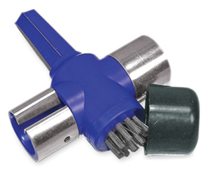
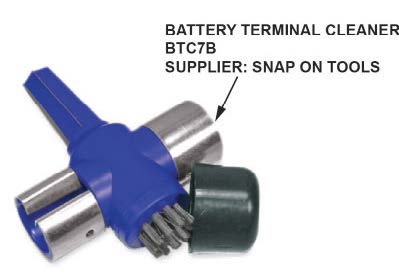
| Battery Terminal Cleaner
|
BTC7B | 1 |
| Engine Balance Bar | VSB02C000041 | 1 |
| Engine Hanger | AAR-T1256 | 2 |
| Subframe Adaptor | VSB02C000016 | 1 |
WARRANTY CLAIM INFORMATION
The normal warranty applies.
| Operation Number |
Description | Flat Rate Time |
Defect Code |
Symptom Code |
Template ID |
Failed Part Number |
| 2181CJ | 2018 Odyssey Replace the transmission (includes alignment and neutral position memorization). Inspect battery terminals, and check torque. | 7.0 hr | 6AN00 | Y4K00 | A19043A | 28102-5MX-A610 |
| 2181CJ | 2019 Odyssey Replace the transmission (includes alignment and neutral position memorization). Inspect battery terminals, and check torque. | 7.0 hr | 6AN00 | Y4K00 | A19043B | 28102-5MX-A610 |
| 2181CK | 2018 Odyssey Replace the transmission (includes alignment and neutral position memorization).
Repair one terminal. |
7.1 hr | 6AN00 | Y4K00 | A19043C | 28102-5MX-A610 |
| 2181CK | 2018 Odyssey Replace the transmission (includes alignment and neutral position memorization). Replace one terminal. | 7.1 hr | 6AN00 | Y4K00 | A19043D | 28102-5MX-A610 |
| 2181CK | 2019 Odyssey Replace the transmission (includes alignment and neutral position memorization).
Repair one terminal. |
7.1 hr | 6AN00 | Y4K00 | A19043E | 28102-5MX-A610 |
| 2181CK | 2019 Odyssey Replace the transmission (includes alignment and neutral position memorization). Replace one terminal. | 7.1 hr | 6AN00 | Y4K00 | A19043F | 28102-5MX-A610 |
| 2181CL | 2018 Odyssey Replace the transmission (includes alignment and neutral position memorization).
Repair both terminals. |
7.5 hr | 6AN00 | Y4K00 | A19043G | 28102-5MX-A610 |
| 2181CL | 2018 Odyssey Replace the transmission (includes alignment and neutral position memorization). Replace both terminals. | 7.5 hr | 6AN00 | Y4K00 | A19043H | 28102-5MX-A610 |
| 2181CL | 2019 Odyssey Replace the transmission (includes alignment and neutral position memorization).
Repair both terminals. |
7.5 hr | 6AN00 | Y4K00 | A19043J | 28102-5MX-A610 |
| 2181CL | 2019 Odyssey Replace the transmission (includes alignment and neutral position memorization). Replace both terminals. | 7.5 hr | 6AN00 | Y4K00 | A19043K | 28102-5MX-A610 |
| 2181CM | 2018 Odyssey Replace the transmission (includes alignment and neutral position memorization). Repair both terminals, and replace the battery (includes internal resistance reset). | 8.0 hr | 6AN00 | Y4K00 | A19043L | 28102-5MX-A610 |
| 2181CM | 2018 Odyssey Replace the transmission (includes alignment and neutral position memorization). Replace both terminals, and replace the battery (includes internal resistance reset). | 8.0 hr | 6AN00 | Y4K00 | A19043M | 28102-5MX-A610 |
| 2181CM | 2019 Odyssey Replace the transmission (includes alignment and neutral position memorization). Repair both terminals, and replace the battery. (includes internal resistance reset). | 8.0 hr | 6AN00 | Y4K00 | A19043N | 28102-5MX-A610 |
| 2181CM | 2019 Odyssey Replace the transmission (includes alignment and neutral position memorization). Replace both terminals, and replace the battery. (includes internal resistance reset). | 8.0 hr | 6AN00 | Y4K00 | A19043P | 28102-5MX-A610 |
Skill Level: Repair Technician
REPAIR PROCEDURE
NOTE
Do not drain the ATF from the old transmission. The replacement (Reman) transmission comes pre-filled with ATF.
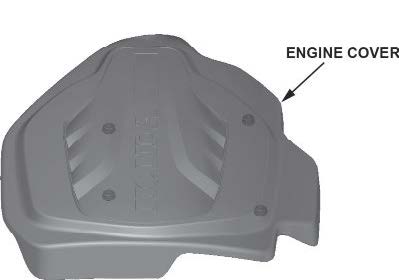
- Remove the engine cover.
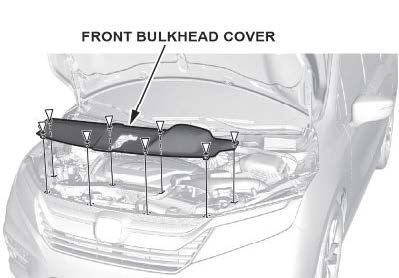
- Remove the front bulkhead cover.
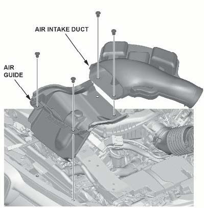
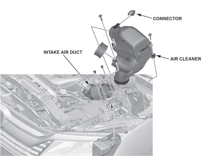
- Remove the air intake duct.
- Remove the air guide.
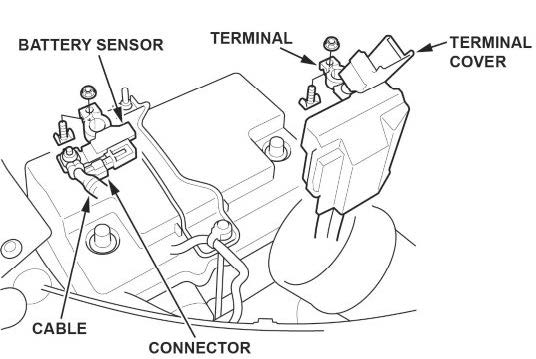
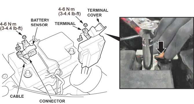
- Disconnect the battery terminals.
5.1 Make sure the ignition is turned to OFF.
5.2 Disconnect and isolate the negative cable with the battery sensor from the battery.
NOTES
- Always disconnect the negative side first.
- To prevent damage, do not hold the connector when removing the battery terminal.
- Do not disconnect the battery sensor from the cable.
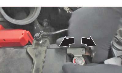
5.3 Open the terminal cover.
5.4 Disconnect the terminal from the battery.

- Remove the setting plate.
- Remove the battery cover.
- Remove the battery.
- Remove the battery bottom cover.
- Disconnect the battery fan motor connector.

- Remove the intake air duct.
- Remove the air cleaner.
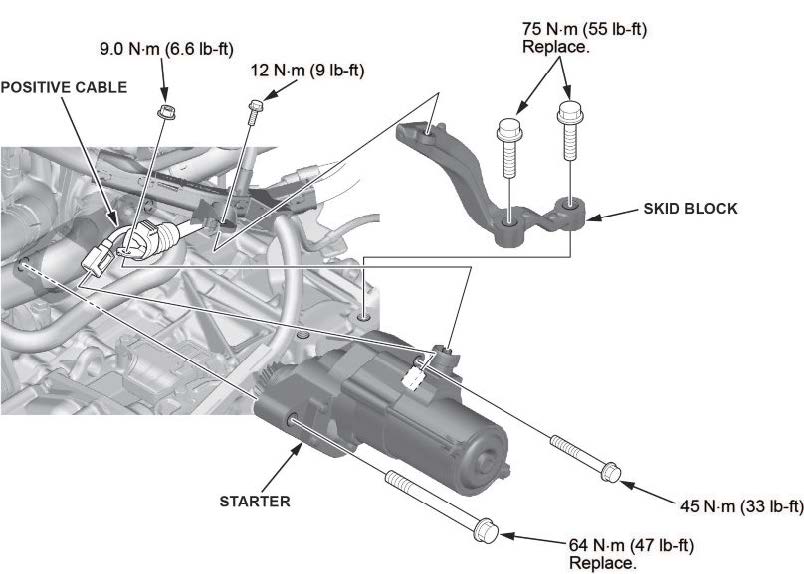
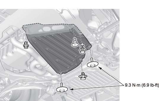
- Remove the skid block.
- Disconnect the positive cable from the starter.
- Remove the starter and connector.
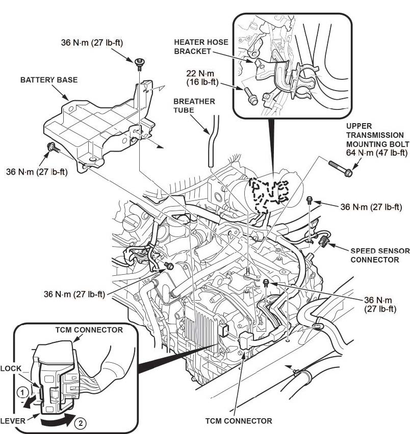
- Remove the battery base.
- Disconnect the breather tube.
- Disconnect the TCM connector.
- Remove the upper transmission mounting bolt.
- Disconnect the speed sensor.
- Remove the heater hose bracket.
- Remove the harness bracket bolts.
- Raise the vehicle on a lift.
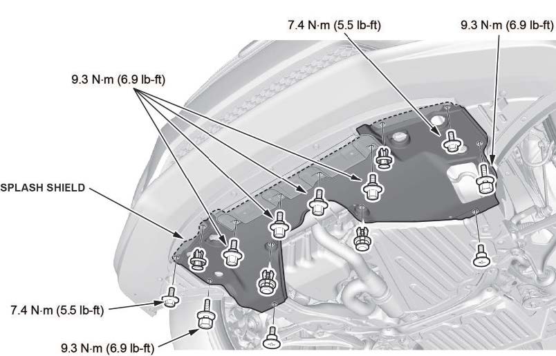
- Remove the splash shield.
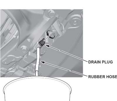
- Drain the coolant.
25.1 Install a rubber hose on the radiator.
25.2 Loosen the drain plug, and drain the coolant.
- Lower the vehicle.
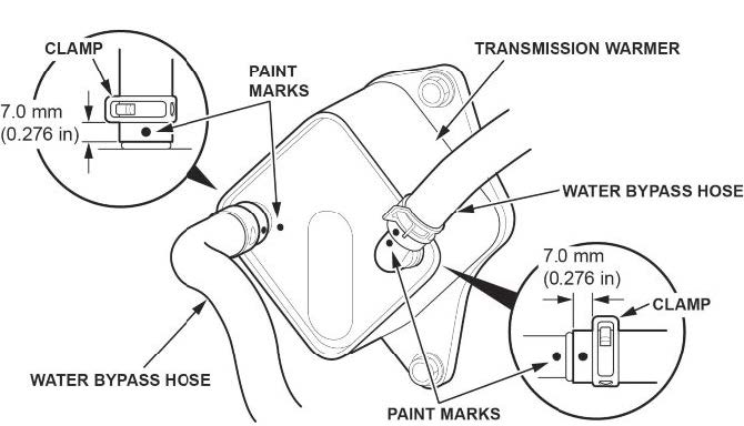
- Disconnect the water bypass hoses from the transmission warmer.
NOTE
To prevent damage, do not bend the pipes excessively.
- Install the engine support hanger.
NOTES
- Be careful when working around the windshield.
- Two sets of AAR-T1256 are required for stacking additional cross section bars.
- Be careful not to damage the hood opener cable when installing the engine support hanger at the front bulkhead.
28.1 Remove the front damper caps.
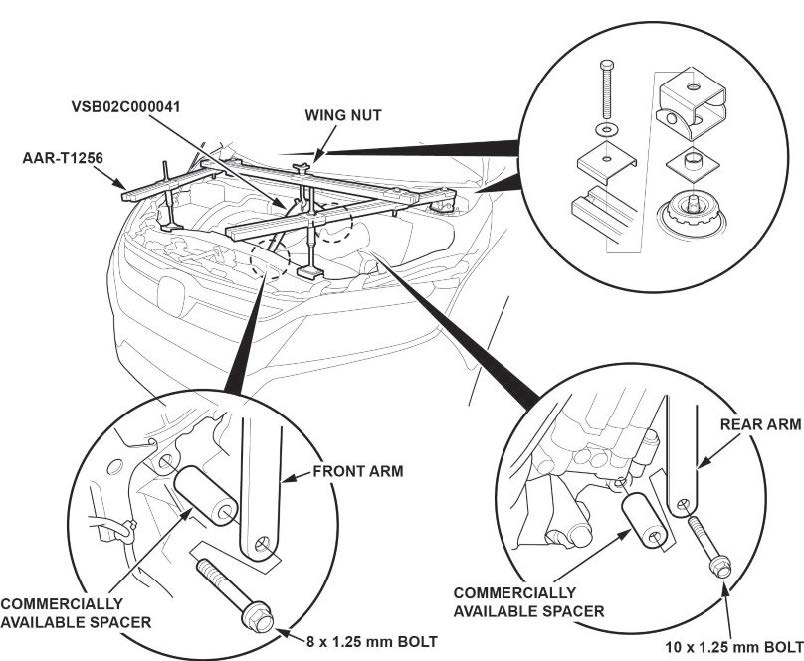
28.2 Install the engine hanger balance bar.
28.2.1 Attach the front arm to the front cylinder head with a commercially available spacer and a 10 x 1.25 mm bolt.
28.2.2 Attach the rear arm to the rear cylinder head with a commercially available spacer and a 10 x 1.25 mm bolt.
28.3 Install the engine support hanger as shown, and attach the hook to the slotted hole in the engine hanger balance bar. Tighten the wing nut by hand, and lift and support the engine/transmission.
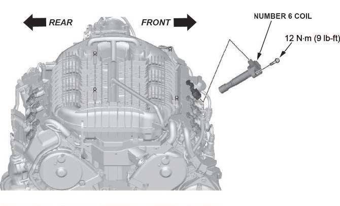
- Remove coil number 6.
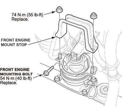
- Remove the front engine mount stop and front engine mount mounting bolt.
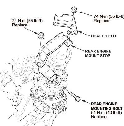
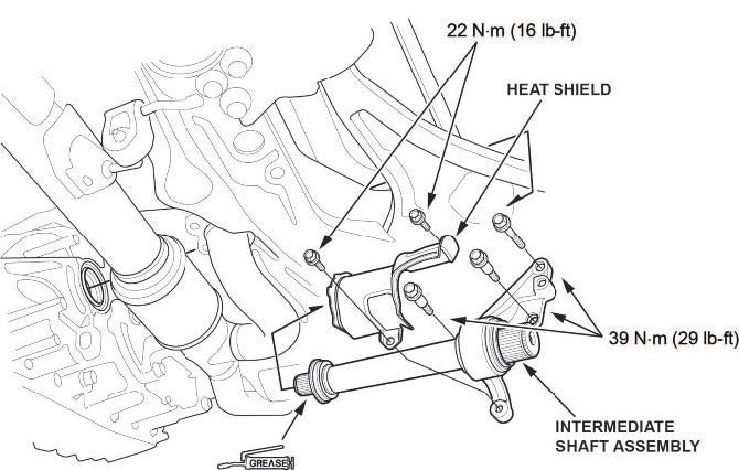
- Remove the rear engine mount stop, heat shield, and rear engine mount mounting bolt.
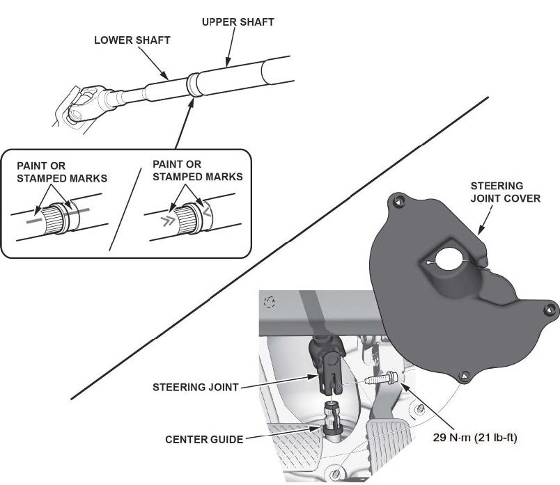
- Disconnect the steering joint.
NOTE
Be careful not to pull out the lower shaft from the upper shaft. If it separates, use the aligning paint or stamped marks on the shafts to align them.
- Remove the transmission undercover.
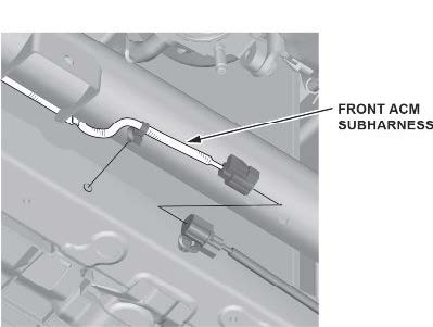
- Disconnect the front ACM (active control engine mount) sub harness.
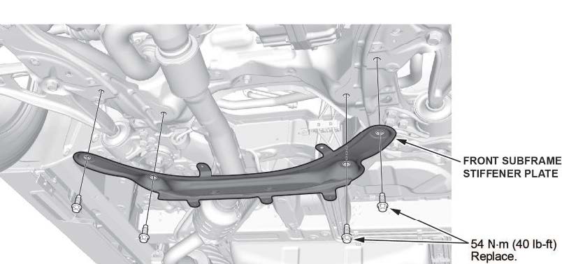
- Remove the front subframe stiffener plate.
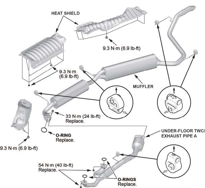
- Remove the under-floor TWC and exhaust pipe.
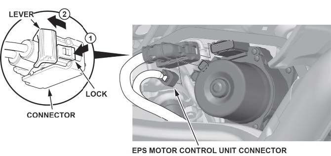
- Disconnect the EPS motor control unit connector.
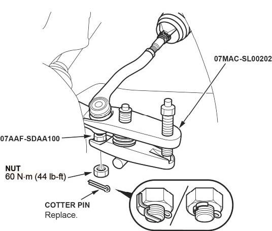
- Disconnect both tie rod end ball joints.
40.1 Remove the cotter pin.
40.2 Remove the nut.
40.3 Disconnect the tie-rod end ball joint from the knuckle using a ball joint thread protector and a ball joint remover.
NOTES
- Be careful not to damage the ball joint boot when using the ball joint remover.
- During installation, install the new cotter pin after tightening the nut, and bend its end as shown.
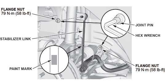
- Disconnect both lower stabilizer links.
41.1 Remove the flange nuts while holding the respective joint pin with a hex wrench.
41.2 Remove the stabilizer link.
NOTE
The stabilizer link has a paint mark. The left stabilizer link is marked with green paint, and the right stabilizer link is marked with blue paint.
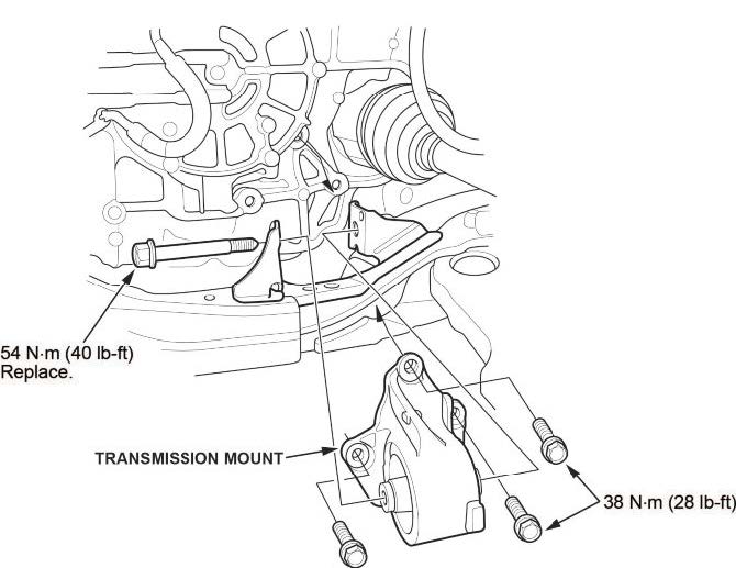
- Remove the transmission mount.
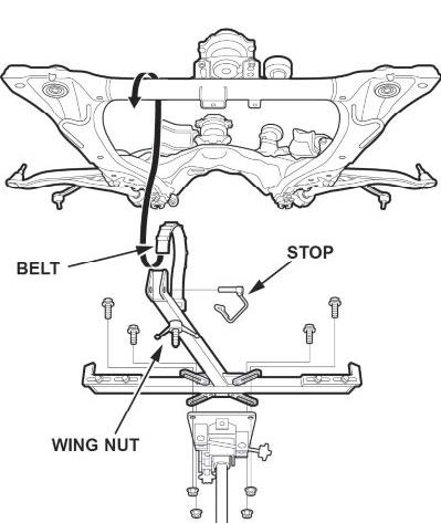
- Install the front subframe adapter tool.
43.1 Attach the subframe adapter to the front subframe by looping the belt over the front of the front subframe, then secure the belt with its stop, and tighten the wing nut.
43.2 Raise a transmission jack, line up the slots in the subframe adapter arms with the bolt holes on the transmission jack base, then securely attach them with four bolts.
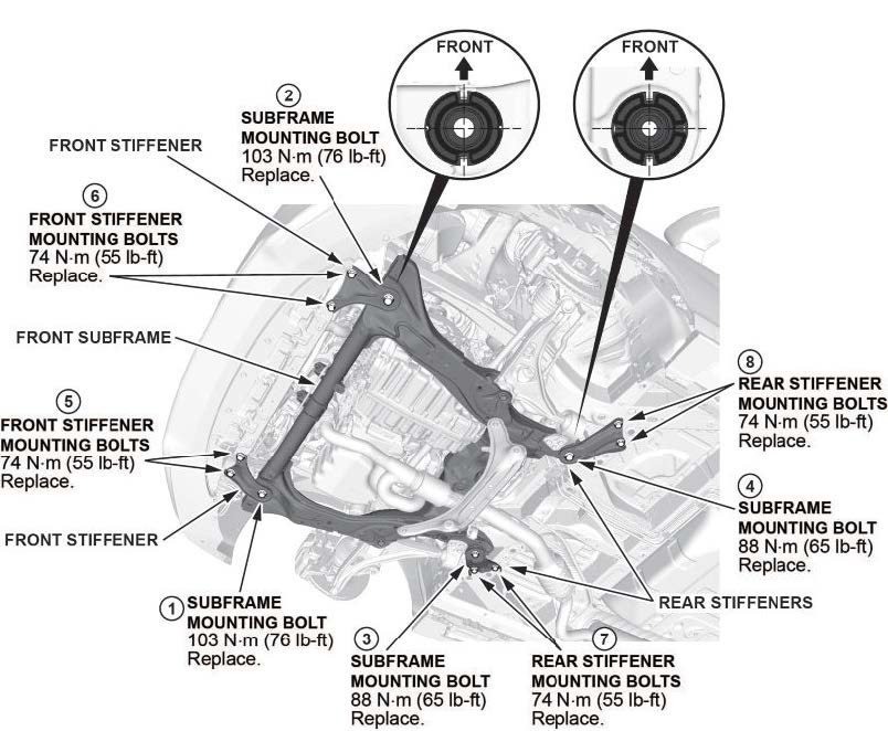
- Remove the front subframe.
NOTES
During installation do the following:
- After loosening the subframe bolts, be sure to replace them with new ones.
- Lift the subframe up to the body, and loosely install the new subfrarme mounting bolts, new front stiffener mounting bolts, front stiffeners, new rear stiffener mounting bolts, and rear stiffeners.
- Tighten the subframe mounting bolts to the torque specification as shown.
- Check all of the subframe mounting bolts, and tighten them if necessary.
- Support the transmission with a transmission jack.
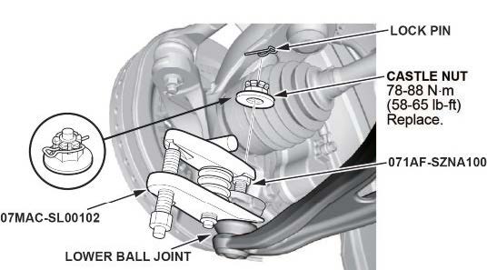
- Disconnect both lower arm ball joints.
46.1 Remove the lock pin from the lower arm ball joint.
NOTE
During installation, install the lock pin as shown after tightening the castle nut.
46.2 Remove the castle nut.
NOTES
- Use a new castle nut when installing.
- Torque the castle nut to the lower torque specification, then tighten it only far enough to align the slot with the ball joint pin hole. Do not align the castle nut by loosening it.
46.3 Disconnect the lower ball joint from the knuckle using the ball joint thread protector and the ball joint remover.
NOTES
- Be careful not to damage the ball joint boot when installing the ball joint remover.
- During installation do the following:
- Be careful not to damage the ball joint boot when connecting the knuckle.
- Degrease the ball joint before connecting the threaded section and the tapered portion of the ball joint pin, the ball joint connecting hole, the threaded section, and the mating surfaces of the castle nut.
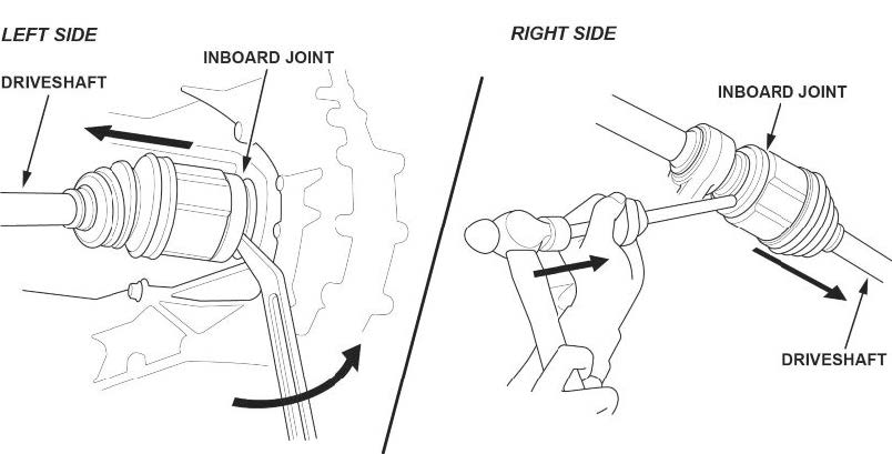
- Disconnect both inner driveline joints.
NOTES
Secure the driveshaft to the body on both sides with a nylon strap.
- Left driveshaft
47.1.1 Pry the inboard joint using a pry bar.
NOTE
Be careful to not damage the oil seal or the end of the inboard joint with a pry bar.
47.1.2 Remove the driveshaft as an assembly.
NOTE
Do not pull on the driveshaft, because the inboard joint may come apart. Pull the inboard joint straight out to avoid damaging the oil seal.
- Right driveshaft
47.2.1 Drive the inboard joint off of the intermediate shaft using a drift punch and a hammer.
47.2.2 Remove the driveshaft as an assembly.
NOTES
- Do not pull on the driveshaft, because the inboard joint may come apart. Pull the inboard joint straight out.
- Use new snap rings when installing the driveshaft.
- Remove the intermediate shaft assembly.
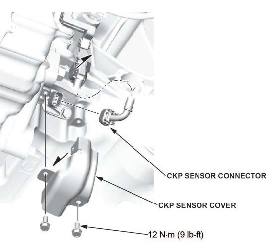
- Disconnect the CKP sensor connector.
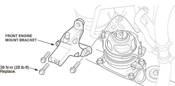
- Remove the front engine mount bracket.
- Disconnect the transmission ground strap.
- Remove the torque converter cover.
- Remove the torque converter bolts.
- Remove the remaining transmission mounting bolts.
- Remove the transmission.
- Remove the dowel pins, and install them on the new transmission.
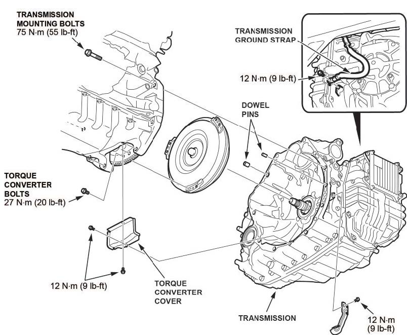
- Install the new transmission.
- Install all removed parts in the reverse order of removal except the intake air duct and the front bulkhead cover. The battery terminals will still need to be inspected.
NOTES
- Make sure to replace all must-replace parts.
- The reman transmission is prefilled with ATF. It does not need to be filled.
- Use new snap rings when installing the drivelines.
- Fill the cooling system with coolant.
At coolant change: 7.4 L (1.90 US gal) with coolant reservoir included.
- Do the keyless access registration.
- Go to BATTERY TERMINAL INSPECTION.
BATTERY TERMINAL INSPECTION
- Inspect the positive and negative battery terminals.
NOTICE
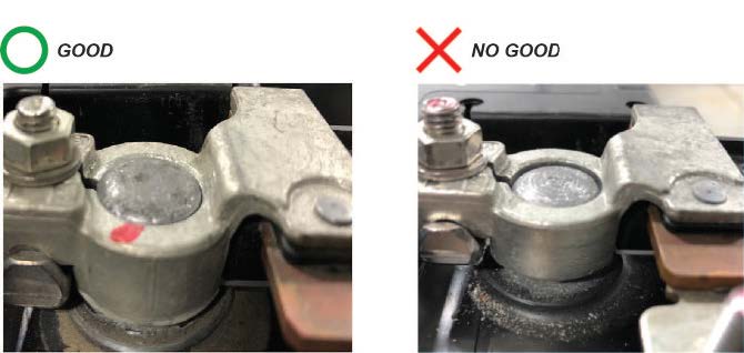
- Battery terminal installation on this vehicle is critical. Failure to follow the terminal installation or inspection procedures could cause electrical problems, stalling, and/or DTCs to set. Do not over torque the terminals, and do not use an impact gun.
- Battery terminal installation must be level or below the post. See GOOD and NO GOOD example pictures.
Compare both of the battery terminals to the examples below.

Do the battery terminals look like the good example?
Yes – Go to step 2.
No – Go to TERMINAL REPAIR.
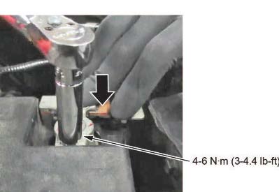
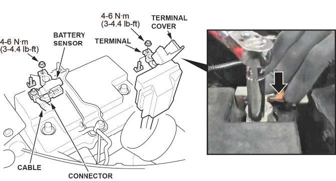
- While holding down the terminal, torque both positive and negative clamps to 4-6 N•m (35-53 lb-in).
NOTE
Do not over torque the terminal.
- Make sure the connection is tight by wiggling the terminals back and forth.

Are both terminals secure?
Yes – Apply multipurpose grease to the terminals to prevent corrosion, and install the air intake duct and the bulkhead cover. Then, do the following steps:
3.1 Check the front-end alignment.
3.2 Do the VSA Sensor Neutral Position Memorization procedure.
3.3 Test-drive the vehicle, and confirm the repair.
No – Go to TERMINAL REPAIR.
TERMINAL REPAIR
- Remove the terminal or terminals, and clean the post using an approved battery terminal cleaner or equivalent.
1.1 Make sure the ignition is turned to OFF.
1.2 Disconnect and isolate the negative cable with the battery sensor from the battery.
NOTES
- Always disconnect the negative side first.
- To prevent damage to the connector, do not hold it when removing the battery terminal.
- Do not disconnect the battery sensor from the cable.
1.3 Open the terminal cover.
1.4 Disconnect the terminal from the battery.
- While holding down the terminal, torque both positive and negative clamps to 4-6 N•m (35-53 lb-in).
NOTES
- Do not over torque the terminal.
- Always connect the positive side first.
- Compare both of the battery terminals to the examples below.
Do the battery terminals look like the good example?
Yes – Go to step 4.
No – Go to REPLACE BATTERY TERMINAL.
- Make sure the connection is tight by wiggling the terminals back and forth.

Are both terminals secure?
Yes – Apply multipurpose grease to the terminals to prevent corrosion, and install the air intake duct and the bulkhead cover. Then do the following steps:
- Check the front-end alignment.
- Do the VSA Sensor Neutral Position Memorization procedure.
- Test-drive the vehicle, and confirm the repair.
No – Go to REPLACE BATTERY TERMINAL.
REPLACE BATTERY TERMINAL
- Remove the battery terminal that does not sit at or below the top of the post.
- Install a new terminal, and torque the terminal and clamp nut to 4-6 N•m (35-53 lb-in) while holding it down.
NOTES
- Always disconnect the negative side first.
- To prevent damage, do not hold the connector when removing the battery terminal.
- Do not disconnect the battery sensor from the cable.
- Compare both of the battery terminals to the examples below.

Do the battery terminals look like the good example?
Yes – Go to step 4.
No – Go to BATTERY REPLACEMENT, BATTERY RESISTANCE RESET PROCEDURE.
- Make sure the connection is tight by wiggling the terminals back and forth.
Are both terminals secure?
Yes – Apply multipurpose grease to the terminals to prevent corrosion, and install the air intake duct and the bulkhead cover. Then, go do the following steps:
- Check the front-end alignment.
- Do the VSA Sensor Neutral Position Memorization procedure.
- Test-drive the vehicle, and confirm the repair.
No – Go to BATTERY REPLACEMENT, BATTERY RESISTANCE RESET PROCEDURE.
BATTERY REPLACEMENT, BATTERY RESISTANCE RESET PROCEDURE
- Disconnect the battery terminals.
1.1 Make sure the ignition is turned to OFF.
1.2 Disconnect and isolate the negative cable with the battery sensor from the battery.
NOTES
- Always disconnect the negative side first.
- To prevent damage to the connector, do not hold it when removing the battery terminal.
- Do not disconnect the battery sensor from the cable.
1.3 Open the terminal cover.
1.4 Disconnect the terminal from the battery.

- Remove the setting plate.
- Remove the battery cover.
- Remove the battery.
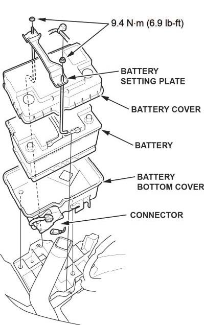
- Install a new battery. Then reinstall the battery cover, and the setting plate in the reverse order of removal.
- While holding down the terminal, torque both positive and negative clamps to 4-6 N•m (35-53 lb-in).
NOTES
- Do not over torque the terminal.
- Always connect the positive side first.
- Compare both of the battery terminals to the examples below.

Do the battery terminals look like the good example?
Yes – Go to step 8.
No – Remove the terminal, and reinstall the terminals, then go to step 7.
- Make sure the connection is tight by wiggling the terminals back and forth.

Are both terminals secure?
Yes – Apply multipurpose grease to the terminals to prevent corrosion, and install the air intake duct and the bulkhead cover. Then go to BATTERY INTERNAL RESISTANCE RESET.
No – Remove and reinstall the terminals, then go to BATTERY INTERNAL RESISTANCE RESET.
BATTERY INTERNAL RESISTANCE RESET
NOTE
Do this procedure only if the battery was replaced.
- Make sure all electrical systems (A/C, audio, lights, etc) are turned off.
- Turn the ignition to OFF.
- Turn the ignition to ACCESSORY.
- Turn the ignition to ON.
- Start the engine, and let it idle for 1 minute or more.
- Turn the ignition to OFF.
- Repeat steps 3 thru 6 at least four times.
NOTE
The internal resistance of the battery may not be updated if the engine starts up immediately from the OFF position.
It has to go through the ACCESSORY and ON position.
- Turn the ignition to ON.
- Connect the i-HDS and select PGM-FI.
- Check IDLE STOP INHIBIT (BATTERY DETERIORATION) in the Data List.
Normal – The battery internal resistance test is complete.
INHIBITED – Replace the battery, then do the battery internal resistance reset procedure again.
- Turn the ignition to OFF, and disconnect the i-HDS.
- Check the front-end alignment.
- Do the VSA Sensor Neutral Position Memorization procedure.
- Test-drive the vehicle, and confirm the repair.
END
2 Affected Products
Vehicle
| MAKE | MODEL | YEAR |
| HONDA | ODYSSEY | 2018-2019 |
16 Associated Documents
Remedy Instructions and TSB
RCRIT-19V299-2354.pdf 4846.634KB
 Loading...
Chronology
RMISC-19V299-0249.pdf 12.829KB
Loading...
Recall Acknowledgement
RCAK-19V299-8161.pdf 384.163KB
Loading...
DEFECT INFORMATION REPORT
RMISC-19V299-2515.pdf 149.435KB
Loading...
Defect Notice 573 Report
RCLRPT-19V299-5941.PDF 213.779KB
Loading...
Manufacturer Notices(to Dealers,etc) – April 12, 2019
RCMN-19V299-3846.pdf 213.823KB
Loading...
Remedy Instructions and TSB
RCRIT-19V299-1782.pdf 4784.157KB
Loading...
Remedy Instructions and TSB
RCRIT-19V299-2603.pdf 3289.759KB
Loading...
Remedy Instructions and TSB
RCRIT-19V299-3867.pdf 4812.272KB
Loading...
ISSUED Owner Notification Letter(Part 577) – Owner Notification Letter (Z4J
RCONL-19V299-8652.pdf 112.541KB
Loading...
ISSUED Owner Notification Letter(Part 577) – Owner Notification Letter (Y4K)
RCONL-19V299-3310.pdf 310.358KB
Loading...
Remedy Instructions and TSB
RCRIT-19V299-5197.pdf 5506.941KB
Loading...
Statement by American Honda Regarding Transmission Control Unit Software Recall: 2018-2019 Honda Odyssey Touring and Touring Elite
RMISC-19V299-0933.pdf 74.873KB
Loading...
Recall Quarterly Report #1, 2019-2
RCLQRT-19V299-4154.PDF 211.153KB
Loading...
Recall Quarterly Report #3, 2019-4
RCLQRT-19V299-3346.PDF 211.354KB
Loading...
Recall Quarterly Report #2, 2019-3
RCLQRT-19V299-1258.PDF 211.256KB
Loading...
Latest Recalls Documents
For the Latest and Most Recent Recalls Information Visit the link below…
https://www-odi.nhtsa.dot.gov/acms/cs/documentList.xhtml?docId=19V299&docType=RCL
- Extended life formulation 5 years/60,000 miles
- Better cooling performance
- Performance under extreme operating conditions -34º to 228ºF
- Pre-mixed DO NOT add water
- Contains NO silcate and borates
- 1 GALLON ENGINE ANTIFREEZE/COOLANT: Fully compatible with other extended life antifreeze/coolants. This item contains a bittering agent called Denatonium Benzoate.
- PROTECTS: Advanced formulation prevents rust & corrosion protecting all engine cooling system components
- DESIGNED FOR ASIAN VEHICLES: Recommended for use with Acura, Honda, Infiniti, Mitsubishi, Nissan, Subaru, and Suzuki vehicles that require a BLUE Phosphate-enhanced Organic Acid Technology (POAT) formula
- GUARANTEED: When installed as part of a complete flush and fill, PEAK guarantees this coolant will provide service life protection of up to 150,000 miles or 5 years.
- 50/50 PREDILUTED FOR QUICK TOP OFFS: Already diluted to make topping off your cooling system a breeze

- Honda 08C50-C321S02 coolant replaced 08C50-C321S01
- Newer formula
- Type 2 ready to use 50/50 blend
- Genuine OEM Honda
- Use for any motorcycle, ATV, UTV, snowmobile, etc

- Newer formula
- 50/50 blend ready to use
- Genuine OEM Honda
- Use for any motorcycle, ATV, UTV, snowmobile, etc.
- CONTAINS: Water 7732-18-5, Ethylene Glycol 107-21-1, Diethylene Glycol 111-46-6. Proprietary Inhibitors (NJTSRN217).
- 5 year/150, 000 mile . Silicate-free, long-life, phosphate Hybrid Organic Acid Technology chemistry
- Formulated to replace the OEM fluid in Asian make vehicles such as Honda, Nissan, KIA, Hyundai and others requiring a blue, silicate free HOAT antifreeze/coolant
- The long life formula provides protection for all cooling system metals from rust and corrosion. The silicate free, borate free formula helps protect against harmful scale and deposits
- Meets the following OEM and industry specifications: Hyundai/KIA MS 591-08, Mitsubishi ES-64217, JIS K 2234-1994, Ford WSS-M97B55-A, ASTM 3306, ASTM D4985, Federal Specification A-A-870A
- Contains 30 – 50 ppm of denatonium benzoate as a bittering agent
- CONTAINS ALUGARD PLUS FOR COMPATIBLITY WITH ALL ETHYLNE GLYCOL-BASED COOLANTS in automobiles and light duty trucks.Fit Type: Universal
- FIGHTS CORROSION, SCALING AND RUST while protecting all cooling system metals (including aluminum)
- HIGH-QUALITY ADDITIVES PROTECT AGAINST LEAKS and won’t harm gaskets, hoses, plastics or original vehicle finish
- PRE-MIXED YELLOW FORMULA IS READY-TO-USE in a 50/50 ratio with deionized water to protect all modern engine components from winter freezing (-34F) and summer boiling (265F).
- To use it in all makes and models designed to use ASTM D3306

- OUR CYCLEMAX PACK CONTAINS: Four Quarts for Honda HP Coolant 50/50 Blend 08C50-C321S02 along with a Convenient Disposable Funnel
- QUALITY YOU CAN COUNT ON: Includes premium quality products to provide exceptional performance and protection for your Honda engine.
- COMPATIBILITY AND CONVENIENCE: Developed specifically for use in aluminum engines. It uses high-tech organic Non-Abrasive Corrosion Inhibitor instead of silicates for maximum protection. Advanced Type-2 Blue formula is 100% compatible with and replaces the original Green coolant. Protects from -34 °F freeze point to 265 °F (at 15 PSI) boiling point. Ready to use straight from the bottle 50/50 blend.

- 1 Gallon Jug of Prestone AF2100 Antifreeze
- 1 ANF Brands Sponge
- Compatible with all vehicles, including all makes, models, years, and fluid colors; supports OAT, POAT, HOAT & IAT.
- Provides antifreeze protection down to -34°F and antiboil/overheat protection up to +265°F.
- Ready to Use Formula: Prediluted 50/50 solution. contains a bittering agent.

- Allows color matching of caps for dedicated adapters.
- Cooling System fill kit prevents spills and trapped air. Trapped air pockets may cause erratic cooling system and heater performance.
- 5” Extension Bar and 45° Elbow allow access to caps under shrouds or at an angle.
- USPTO Patent No: US10519019B2
- 1 GALLON ENGINE ANTIFREEZE/COOLANT: Fully compatible with other extended life antifreeze/coolants. This item contains a bittering agent called Denatonium Benzoate.
- PROTECTS: Advanced formulation prevents rust & corrosion protecting all cooling system components
- DESIGNED FOR EUROPEAN VEHICLES: Recommended for use with BMW, Jaguar, Volvo, and other European vehicles that require a BLUE Silicate-Enhanced Hybrid Organic Acid Technology (Si-HOAT) formula
- GUARANTEED: When installed as part of a complete flush and fill, PEAK guarantees this coolant will provide service life protection of up to 150,000 miles or 5 years.
- 50/50 PREDILUTED FOR QUICK TOP OFFS: Already prediluted to make topping off your cooling system a breeze
Last update on 2024-04-23 / Affiliate links / Images from Amazon Product Advertising API
This product presentation was made with AAWP plugin.