| “This site contains affiliate links for which OEMDTC may be compensated” |
NHTSA Campaign Number: 13V382
Manufacturer Honda (American Honda Motor Co.)
Components ENGINE
Potential Number of Units Affected 270
A worn piston may suddenly fail, causing the engine to stall, increasing the risk of a crash.
Summary
Honda is recalling certain model year 2013 Pilot 2WD and 4WD vehicles and certain model year 2013 Odyssey vehicles.
During manufacturing of the engine piston, it is possible that the heat treatment process was not properly applied, resulting in the piston having an insufficient hardness level, making it more susceptible to premature wear.
Remedy
Honda will notify owners, and dealers will replace the engine short block free of charge.
The recall began on September 16, 2013.
Owners may contact Honda at 1-800-999-1009.
Honda’s recall numbers are JB4 (Honda Odyssey) and JB5 (Honda Pilot).
Notes
Owners may also contact the National Highway Traffic Safety Administration Vehicle Safety Hotline at 1-888-327-4236 (TTY 1-800-424-9153), or go to www.safercar.gov.
Check if your Honda has a Recall
A13-075
September 5, 2013
Applies To:
2013 Odyssey – Check the iN VIN status for eligibility
2013 Pilot – Check the iN VIN status for eligibility
Safety Recall: Pistons Out of Specification
(Supersedes 13-075, dated August 27, 2013, to revise the information marked by the black bars)
REVISION SUMMARY
Updated PARTS INFORMATION, REQUIRED MATERIALS, TOOL INFORMATION, repair steps, and multiple photo illustrations.
BACKGROUND
A limited number of Pilot and Odyssey engines may have been assembled with pistons that could be out of specification. Premature piston failure can occur, which may cause the engine to stall.
CUSTOMER NOTIFICATION
Owners of affected vehicles will be sent a notification of this campaign in September 2013.
Do an iN VIN status inquiry to make sure the vehicle is shown as eligible.
New or used vehicles affected by this campaign may be in your vehicle inventory. These vehicles must be repaired before they are sold.
Should a dealership sell an unrepaired vehicle that subsequently causes an injury or damage because of the recalled item, the dealership will be soley responsible to the damaged party, and will be required to defend and indemnify American Honda for any resulting claims. To see if a vehicle in inventory is affected by this campaign, do a VIN status inquiry before selling it
CORRECTIVE ACTION
Replace the short block assembly.
PARTS INFORMATION Common Parts
| P/N | |
| Head bolt (16 required): | 90005-PAA-A01 |
| Intake Cover Gasket: | 17146-R70-A01 |
| Intake Manifold Gasket: | 17105-RCJ-A01 |
| Catalytic Converter Gasket (two required): | 18115-R70-A01 |
| Oil Filter: | 15400-PLM-A02 |
| Nut, Flange (engine mount stopper nuts) (four required): | 90302-S3V-A10 |
| Nut, Self Locking (catalytic convertor) (eight required): | 90212-RCA-A01 |
| Gasket, Prechamber: | 18393-SDB-A00 |
| Gasket, Exhaust Pipe (two required): | 18212-SA7-003 |
| Bolt, Flange (side mount bolt to frame bracket) (two required): | 90163-SDA-A01 |
| Bolt, Flange (side engine mount bolts) (two required): | 90164-SHJ-A00 |
| Retainer (fuel line connector): | 17711-S0X-931 |
| O-Ring (fuel rail o-ring): | 91301-PLC-000 |
| Gasket A, EGR Pipe (EGR pipe gasket): | 18716-R70-A01 |
| Gasket B, EGR Pipe (EGR pipe gasket): | 18719-R70-A01 |
| Gasket, Rear Cylinder (head gasket): | 12261-R70-A01 |
| Gasket, Front Cylinder (head gasket): | 12251-R70-A01 |
| O-Ring (o-rings for coolant pipe) (two required): | 91314-PH7-003 |
| Gasket, Front Water Passage (coolant crossover) (one required): | 19411-P8A-A03 |
| Gasket, Rear Water Passage (coolant crossover) (one required): | 19412-P8A-A02 |
| O-Ring (A/C discharge hose o-ring): | 80872-ST7-000 |
| O-Ring (A/C suction side o-ring): | 80871-ST7-000 |
| Bolt, Flange (special bolt; rear subframe bolt) (two required): | 90161-SHJ-A00 |
| Ring, Snap (left side circlip only): | 44319-SOX-A01 |
| P/N | |
| Engine Short Block: | 10002-RV0-A01 |
| Bolt, Flange (strut to knuckle) (four required): | 90120-SHJ-A00 |
| Nut, Flange (strut to knuckle) (four required): | 90382-SP0-003 |
| Bolt, Flange (subframe bolt) (four required): | 90165-TK8-A00 |
| P/N | |
| Engine Short Block: | 10002-RN0-A11 |
| Bolt, Flange (strut to knuckle) (four required): | 90119-SJC-A00 |
| Nut, Flange (strut to knuckle) (four required): | 90381-SJC-A00 |
| Bolt, Flange (prop shaft bolts) (four required): | 90113-S3V-A00 |
| Bolt, Flange (special bolt, subframe) (four required): | 90165-SHJ-A00 |
| Bolt, Flange (subframe stiffener) (four required): | 90167-SAA-010 |
REQUIRED MATERIALS
| P/N | |
| Antifreeze Coolant Type 2 (3 gallons): | OL999-9011 |
| 0W-20 Engine Oil (5 quarts) | 08798-9036 |
| Power Steering Fluid | 08206-9002 |
TOOL INFORMATION
| Steering Wheel Holder | (Snap-On WA96 or equivalent) |
| Subframe Alignment Pin | 070AG-SJAA10S |
WARRANTY CLAIM INFORMATION Odyssey
| Flat Rate Time: | 10.7 hours (includes alignment) |
| Failed Part: | 10002-RV0-A01 |
| Defect Code: | 5GW00 |
| Symptom Code: | JB400 |
| Skill Level: | Repair Technician |
Operation Number: 1111AJ
| Flat Rate Time: | 10.7 hours (includes alignment) |
| Failed Part: | 10002-RN0-A10 |
| Defect Code: | 5GW00 |
| Symptom Code: | JB500 |
| Skill Level: | Repair Technician |
Operation Number: 1111AJ
REPAIR PROCEDURE
The following service manual procedures have been used in full or in part within this service bulletin. For more detail on these procedures, and torque specifications for some components, refer to the appropriate electronic service manual.
- Engine Oil Replacement
- Battery Terminal Disconnection and Reconnection
- A/C System Recovery/Charging
- Fuel Pressure Relieving
- Steering Gearbox Removal
- Transfer Assembly Removal (Pilot with 4WD)
- Coolant Replacement
- Drive Belt Removal/Installation
- Front Undercover Replacement
- Splash Shield Replacement
- Hydraulic Power Steering Fluid Check/Replacement
- Air Cleaner Removal/Installation
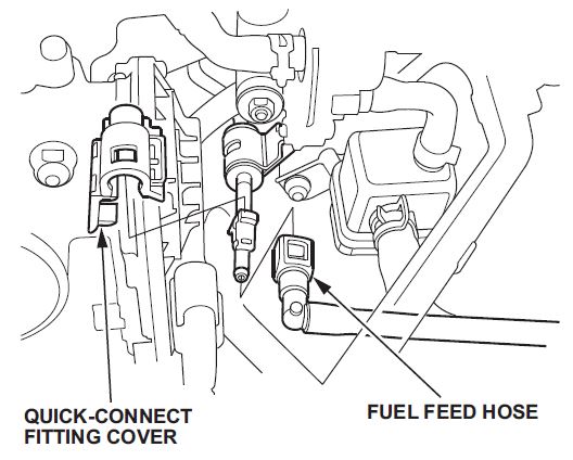
- Fuel Line/Quick-Connect Fitting Removal
- Front Bulkhead Cover Replacement (Pilot only)
- Front Stabilizer Link Removal/Installation
- Front Knuckle/ Hub Bearing Unit Replacement
- Cylinder Head Cover Removal
- Intake Manifold Removal and Installation
- Warm Up TWC Removal/Installation
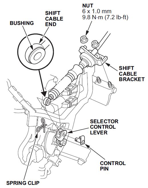
- Transmission Shift Cable Removal and Installation
- Cylinder Head Removal and Installation
- Timing Belt Removal and Installation
- Valve Adjustment
- Subframe Installation Procedure Engine/Transmission Assembly Removal
Engine/Transmission Assembly Removal
- Use fender covers to avoid damaging painted surfaces.
- To avoid damaging any wires and terminals, unplug the circuit connectors carefully while holding the connector portion.
- Mark all wiring and hoses to avoid misconnection. Also, be sure that they do not contact other wiring or hoses, or interfere with other parts.
- Relieve the fuel pressure.
- Wait until the engine is cool, then carefully remove the radiator cap.
- Loosen the drain plug on the radiator, and drain the engine coolant.
- Drain the power steering fluid from the reservoir.
- Do the battery removal procedure.
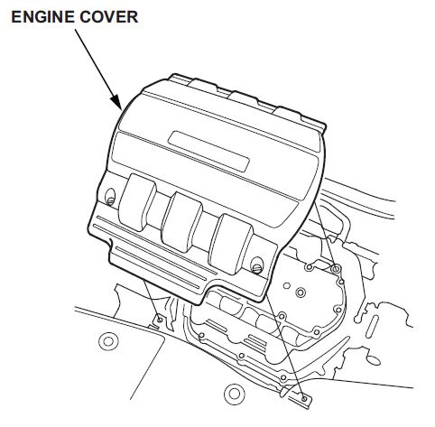
- Remove the engine cover.
- Evacuate the A/C system.
- Separate the A/C suction line at the right strut tower junction, and cover the lines with tape.
- Disconnect the breather pipe, then remove the intake air duct.
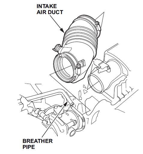
- Remove the air cleaner assembly.
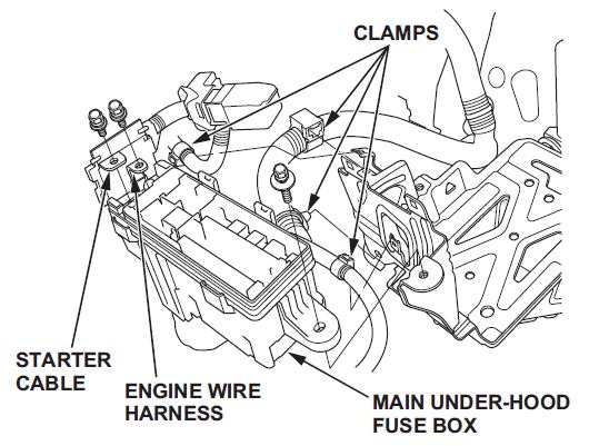
- Odyssey only. Disconnect the engine wire harness and starter cable from the main under-hood fuse box, then remove the main under-hood fuse box and the harness clamps.
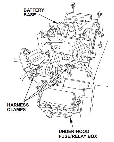
- Remove the harness clamps, then remove the battery base.
- Remove the transmission shift cable from the transmission only.
- Remove the quick-connect fitting cover, then disconnect the fuel feed hose.
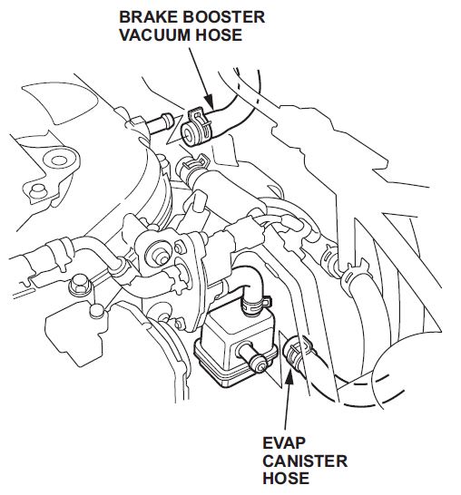
- Disconnect the brake booster vacuum hose and EVAP canister hose.
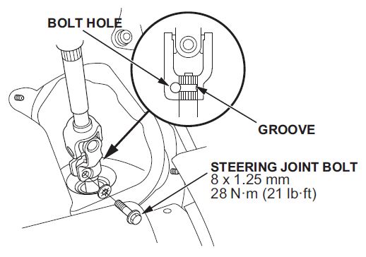
- Remove the steering joint cover, then disconnect the steering joint from the steering gearbox pinion shaft.
NOTE: Hold the steering wheel with the steering wheel holder.
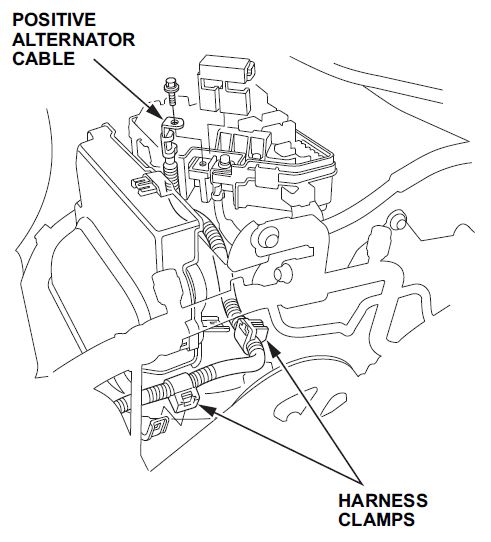
- Pilot only. Remove the harness clamps, then disconnect the positive alternator cable from the under-hood fuse/relay box.
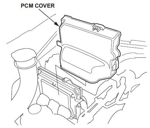
- Remove the PCM cover.
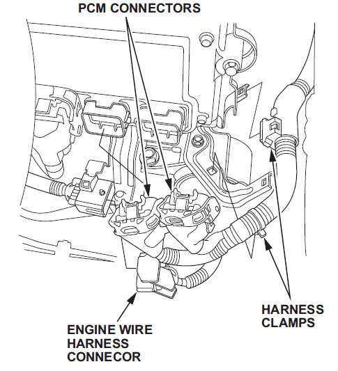
- Remove the harness clamp, and disconnect the PCM connectors.
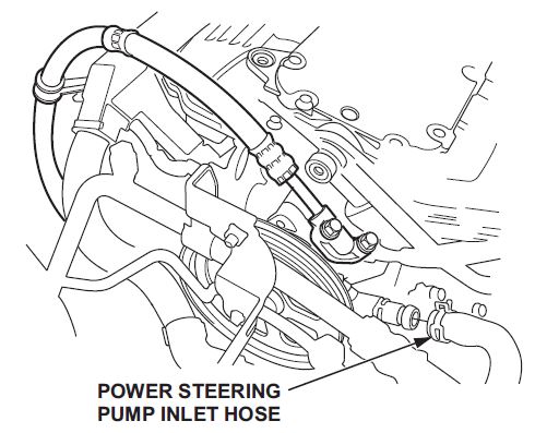
- Disconnect the power steering pump inlet hose.
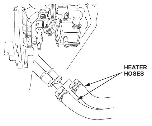
- Disconnect the heater hoses.
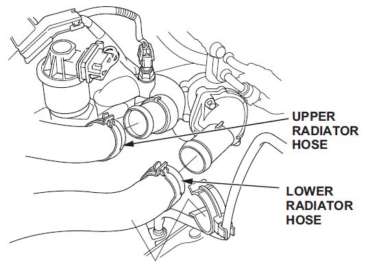
- Disconnect the upper radiator hose and the lower radiator hose at the engine.
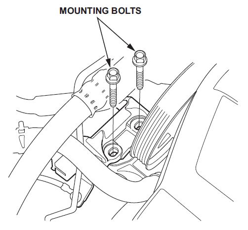
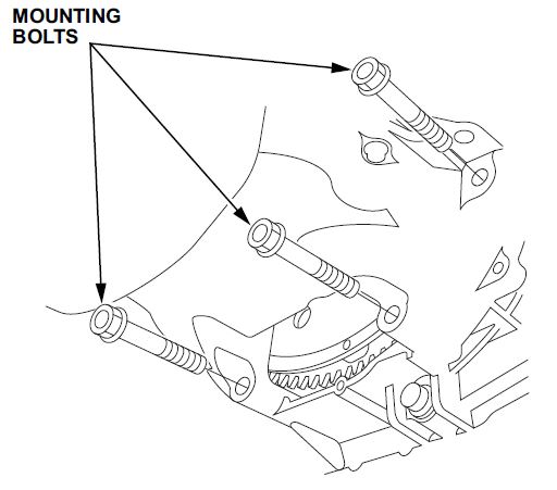
- Remove the mounting bolts from the upper half of the side engine mount bracket.
- Check that the engine/transmission is completely free of any vacuum hoses, fuel hoses, coolant hoses, and electrical connections.
- Raise the vehicle on the lift.
- Remove the front wheels.
- Remove the splash shield and the front undercover.
- Drain the engine oil.
- Drain the ATF.
- Pilot only. Remove the front subframe stiffener.
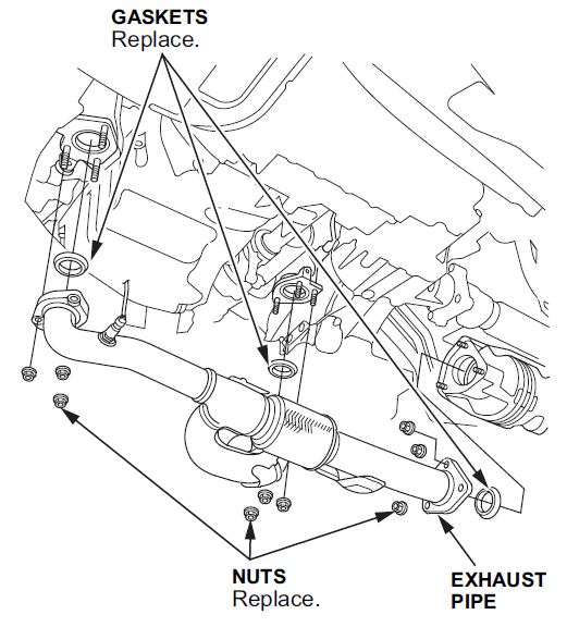
- Remove the exhaust pipe.
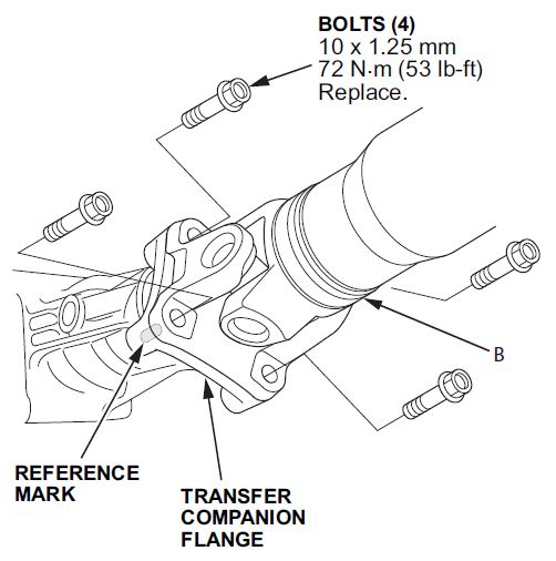
- Pilot only, with 4wd. Remove the bolts, and disconnect the propeller shaft from the transfer companion flange.
NOTE: Be sure to make a reference mark across the propeller shaft and transfer companion flange for reassembly.
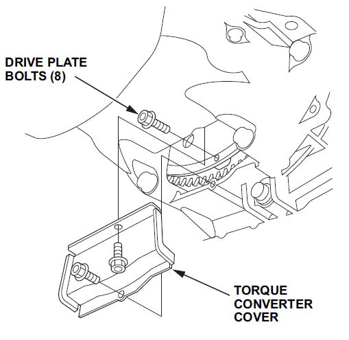
- Remove the torque converter cover from the transmission.
- Remove the drive plate bolts from the torque converter.
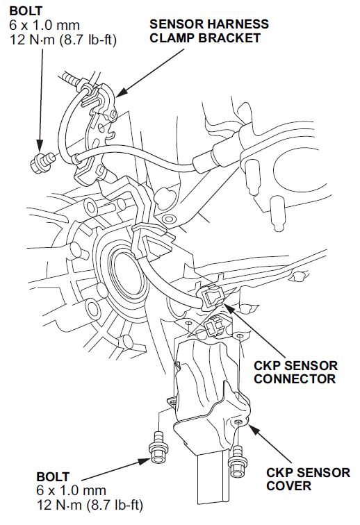
- Disconnect the CKP sensor connector by removing the CKP sensor cover, then disconnecting connector.
- Remove the lower transmission housing bolts.
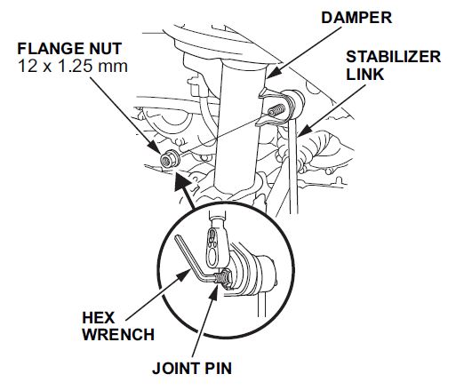
- Separate the stabilizer links from the dampers.
- Remove the ABS sensor from the steering knuckle.
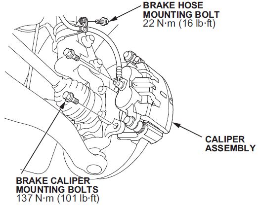
- Remove the front brake calipers.
- Remove the brake line bracket from the damper.
- Remove the two brake caliper bolts.
- Support the brake calipers by hanging them from the dampers with a suitable strap.
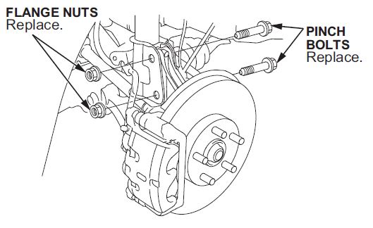
- Separate the knuckles from the dampers by removing the two bolts.
- Disconnect the power steering hose and A/T cooler hose, then plug the line and hose.
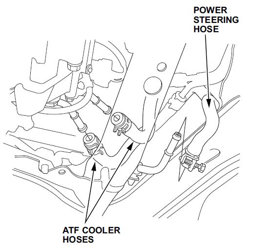
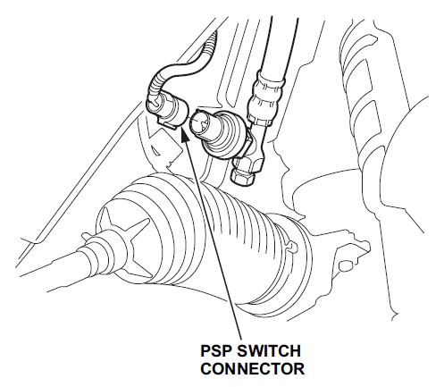
- Disconnect the power steering pressure switch connector.
- Remove the A/C high pressure line from the compressor, and cover the lines with tape.
- Disconnect the electrical connector from the front and rear engine mounts.
- Check that the engine/transmission and subframe are completely free of any hardware, electrical connections, and components.
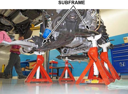
- Prepare the subframe assembly for removal.
- Set up four equal sized jack stands (or equivalent equipment) under the vehicle’s subframe immediate area.
- Lower the vehicle until it is just above the jack stands.
- Position the jack stands (or equivalent equipment) so that they are equally spaced in the front and the back of the subframe.
- Lower the vehicle and set the subframe on the jack stands.
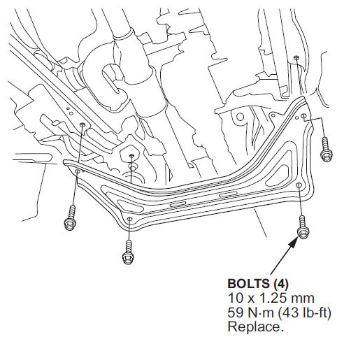
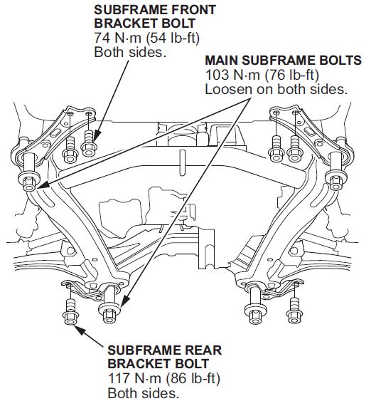
- Remove the four 14 x 1.5 mm main subframe bolts.
- Check that the engine/transmission and subframe are completely free of any hardware, electrical connections, and components.
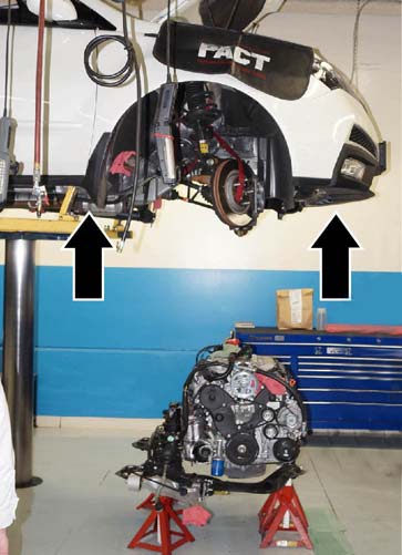
- Slowly raise the vehicle. Make sure there are no components catching on the body.
NOTE: Pilot with 4WD only. Pay close attention to the propeller shaft; it may get snagged on the sway bar.
- Drain the remaining coolant from the drain port at the rear of the engine block. Remove the block heater plug, and let the coolant drain into a suitable container.
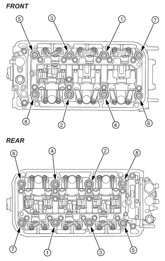
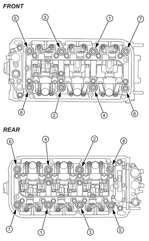
- Remove both cylinder heads. To prevent warping of the cylinder heads, loosen the bolts in sequence 1/3 turn at a time. Repeat the sequence until all of the bolts are loosened.
NOTE: You can remove each head as an assembly.
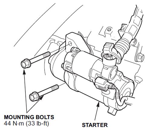
- Remove the starter bolts.
NOTE: Leave the electrical harness connected to the starter. The starter does not need to be removed. Remove the bolts to allow for sufficient clearance when separating the engine from the transmission.
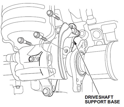
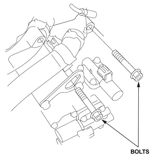
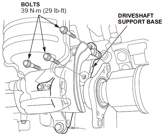
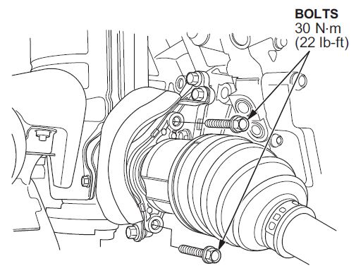
- Remove the driveshaft bearing bracket bolts, and rotate the bearing bracket counter clockwise to gain access to the engine support bracket bolts.
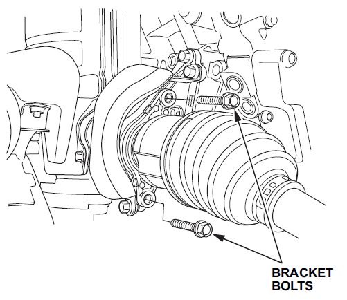
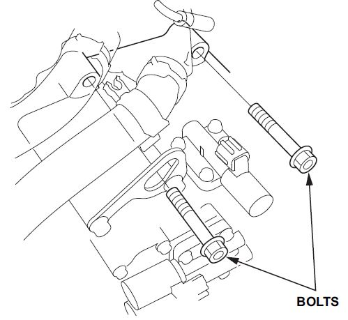
- Remove the engine support bracket bolts.
NOTE: The driveshaft may separate from the transmission when the bolts are removed; however, there is no need to remove the entire driveshaft assembly.
- Remove the rear transmission housing bolts.
- Support the transmission using a jack. Use either a piece of wood or rubber block between the transmission and jack to prevent damage to the transmission housing.
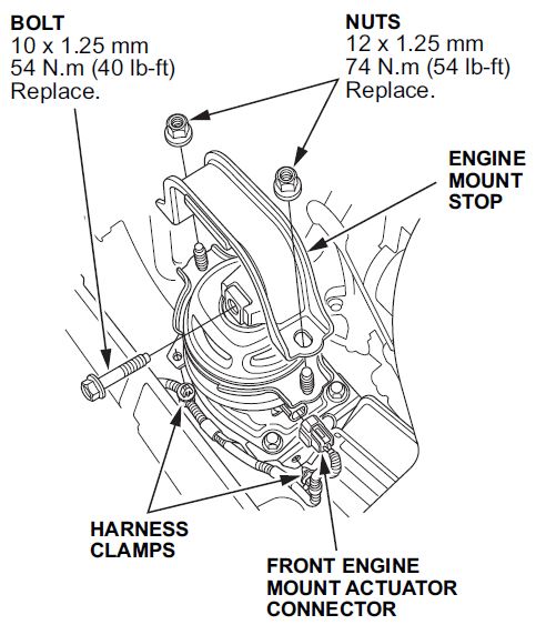
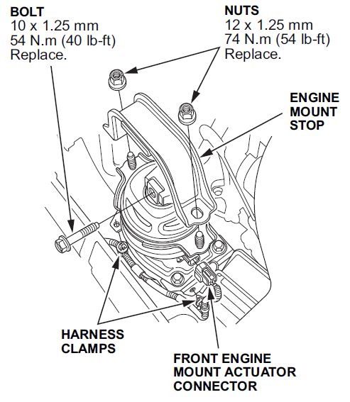
- Remove the front and rear engine mount stop, then remove the bolt.
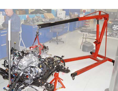
- Use an engine hoist and straps to support the engine block for separation.
NOTE: There are several different methods to support the block. Use the one that best works for you.
- Remove the upper transmission housing mounting bolts.
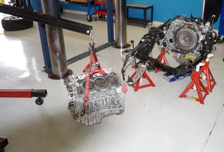
- Lift the engine block from the subframe assembly, being careful not to shift the transmission off the jack.
- Transfer any remaining components from the old engine block to the new engine block including:
- Front and rear engine mount brackets
- Timing belt idler pulleys
- • Torque converter flex plate
- Use an engine hoist and straps to support the new engine block for reattachment to the transmission.
- Reattach the engine block to the transmission in the reverse order of removal.
- Reinstall the front and rear engine mount bolts and engine mount stop.
- Reinstall the engine support bracket bolts.
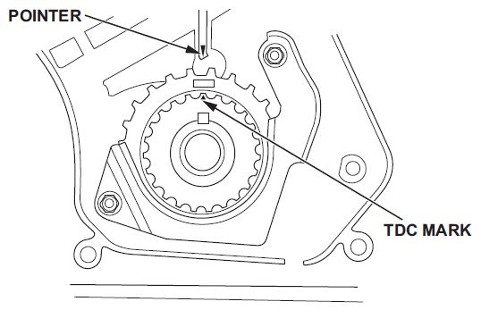
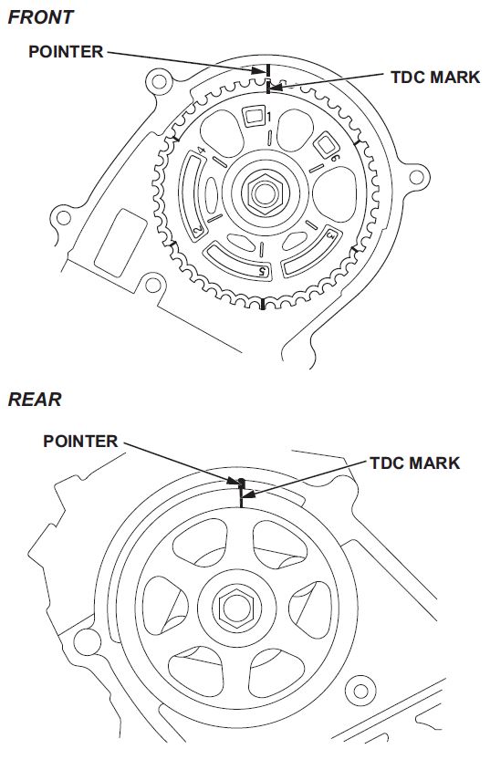
- Verify the camshaft pulleys are at TDC.
- Reinstall the cylinder heads on the engine block.
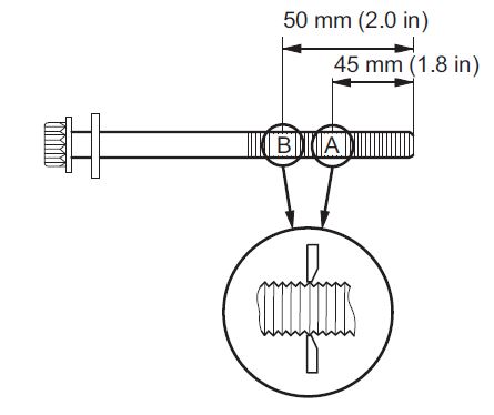
- Measure the diameter of each cylinder head bolt at 50 mm (2.0 in) and 45 mm (1.8 in) from the threaded end of the bolt.
- Reinstall the cylinder heads on the engine block.
- Measure the diameter of each cylinder head bolt at 50 mm (2.0 in) and 45 mm (1.8 in) from the threaded end of the bolt.
NOTE: If either diameter is less than 11.3 mm (0.44 in), replace the cylinder head bolt.
- Apply new engine oil to the threads and under the bolt heads of all cylinder head bolts.
- Torque the cylinder head bolts in sequence to 29 N•m (22 lb-ft) using a beam-type torque wrench.
NOTE: Be sure to tighten each bolt slowly and do not overtighten. If a bolt makes any noise while you are torquing it, loosen the bolt and retighten it from the first step.
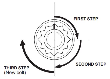
- After torquing the cylinder head bolts, tighten them in two steps (90 degrees per step) in sequence. If you are using a new cylinder head bolt, tighten the bolt an additional 90 degrees.
NOTE: If you tighten a cylinder head bolt beyond the specified angle, go back to step 73 of the procedure. Do not loosen it back to the specified angle.
- Install the remaining engine components in the reverse order of removal.
- Slowly lower the vehicle until it is right above the engine/transmission assembly.
NOTE: Make sure there are no components sticking out that may get caught on the body when the vehicle is being lowered
- Position the subframe for reinstallation to the body.
- Insert the four main subframe bolts and brackets, and tighten them until they are snug.
NOTE: Do not torque the bolts because subframe adjustment will be necessary once the vehicle has been lifted.
- Raise the vehicle.
- Adjust the subframe using the appropriate tool and torque all bolts.
- Reinstall remaining components in the reverse order of removal.
- Refill all fluids and do an alignment.
 Loading...
Loading...
Loading...
Loading...
Loading...
Loading...
Loading...


